If you don’t yet have a 3D printer, here’s an excuse to buy one — print your own tools! I’ve included the STL files so that you can easily print the tools shown here. Please leave a comment if make one of these tools.
I have the Monoprice Mini, which is a fantastic printer for PLA plastics — very accurate — costing only $200. It’s OK on ABS, though parts may warp. Still, I’ve printed more ABS on this printer than PLA, so it’s very usable. Don’t judge the printer by most of the prints shown here; I didn’t print anywhere near the highest resolution.
If you’re curious, I use Fusion 360 for my 3D CAD work. It’s free for hobbyist, you just have to register once per year. It’s relatively easy to use given how powerful the program is (as long as you stay away from lofting, that’s hard).
I had black filament loaded in the printer when I printed most of these tools. If you do print these, I suggest a bright color so that you can find them in your toolbox, and in the case of the crankshaft block, you’re more likely to remember to remove it.
Quick jump:
- Crankshaft block tool
- Clutch alignment tool
- Rear main seal install tool
- 27mm Swingarm Socket
- 10mm offset adapter for drive-shaft bolts
- Center Stand Tab Straightener
- DIY Bag Pump for Air Matress/Sleeping Pad
CRANKSHAFT BLOCK
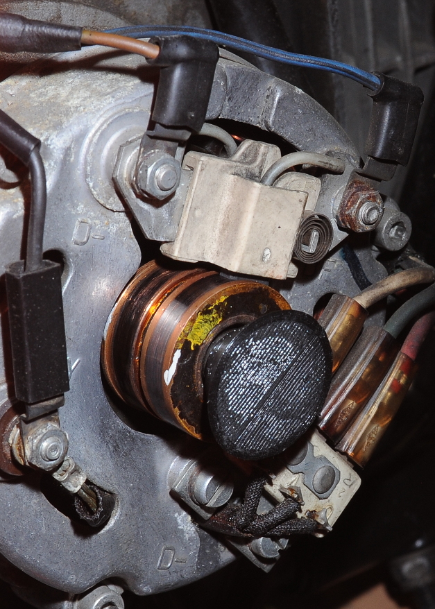
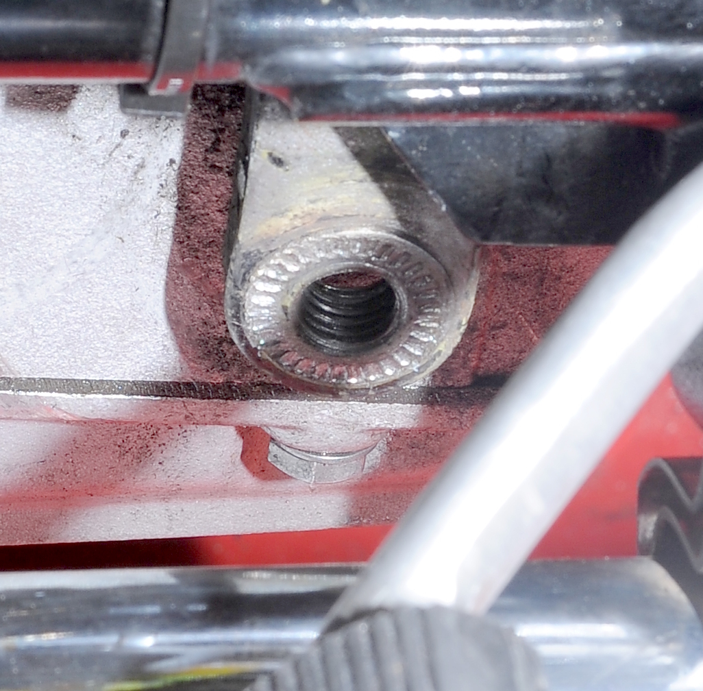
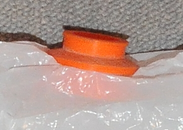
If you search the web you’ll discover many options for backing the crankshaft when removing the flywheel. Here’s another option that’s quick and easy if you have a 3D printer, or know someone who does. You simply insert the 6mm hex head end into your rotor as shown in the second picture and then reinstall the cover. This spacer leaves about 1/8″ inch gap between the cover and the motor so you can tighten the cover against the rotor and prevent the crankshaft from shifting which is bad, very bad!
STL File: crankshaftTool.stl
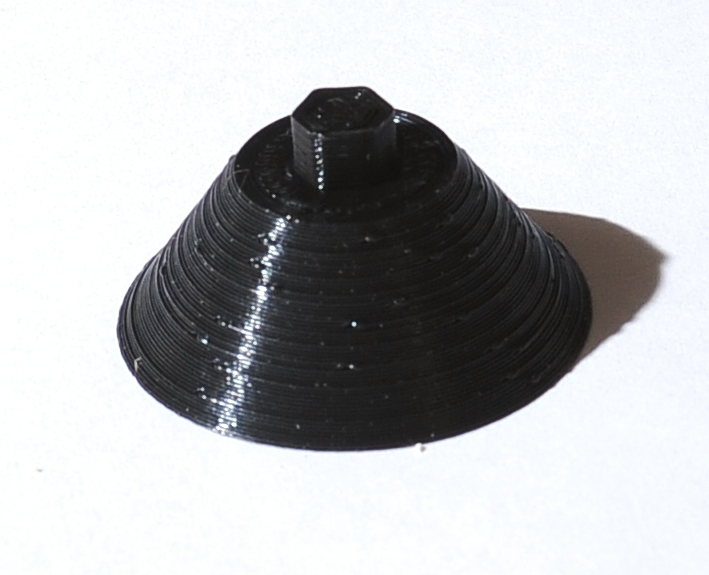
As shown here, the taper ensures that all of the pressure is applied to the bolt head. On my bike, the bolt head is slightly below the face of the rotor. (Note: This is the first time I’ve had the front cover off this bike. I can now see that the electrical system definitely needs some attention!)
 REAR MAIN SEAL INSTALL TOOL
CLUTCH ALIGNMENT TOOL
You can print this clutch alignment tool for a few cents worth of plastic, or you can buy a metal one for $30 or more. It’s the same design that you can find described elsewhere on the web, except that I shortened the 22mm diameter section a bit to fit my printer, which can only print objects smaller than 120mm. It’s quit strong when printed with 4 outer layers and 30% fill. I printed this in PLA. There’s no longer any reason not to have one of these tools in your toolbox, so stop eyeballing it, or trying to use your tranny as an alignment tool.
 You could also design a tool like this with a hollow center to allow a small metal shaft to be inserted (e.g. if you’re building a tool for the older airheads). I briefly thought about doing anyway that so that I could temporarily use the bikes clutch pushrod as part of the tool. This was simpler, and I don’t risk damaging the pushrod.
Makes a great stocking stuffer for all of your airhead friends!
STL File: clutchTool.stl
REAR MAIN SEAL INSTALL TOOL
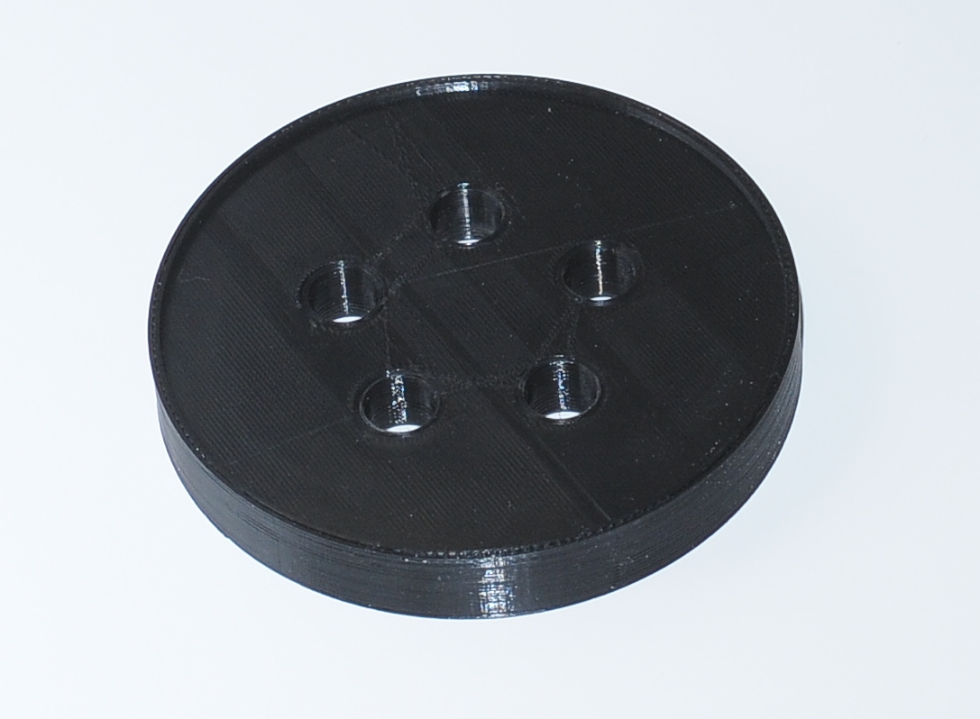
This tool makes an easy job of installing the rear main seal . The tool can be used in one of two ways. In the picture you can see the side with a lip. When this side is placed against the seal, you can install the seal sitting above the case by 2mm. The other side is flat, place it against the seal to install flush.
Start by installing the seal by hand making sure that it’s level to the surface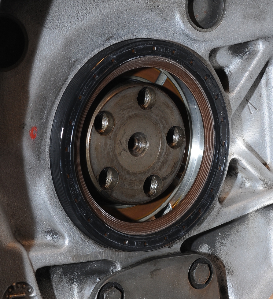
Place the tool over the seal and tighten the flywheel bolts by hand. Then tighten each bolt 1/4 turn at a time until the plastic is against the case. The washers are optional, especially if you’re only going to use the tool a few times. There’s really very little pressure on the plastic.
Here’s the seal installed proud by 2mm like the old-style spring seal I removed.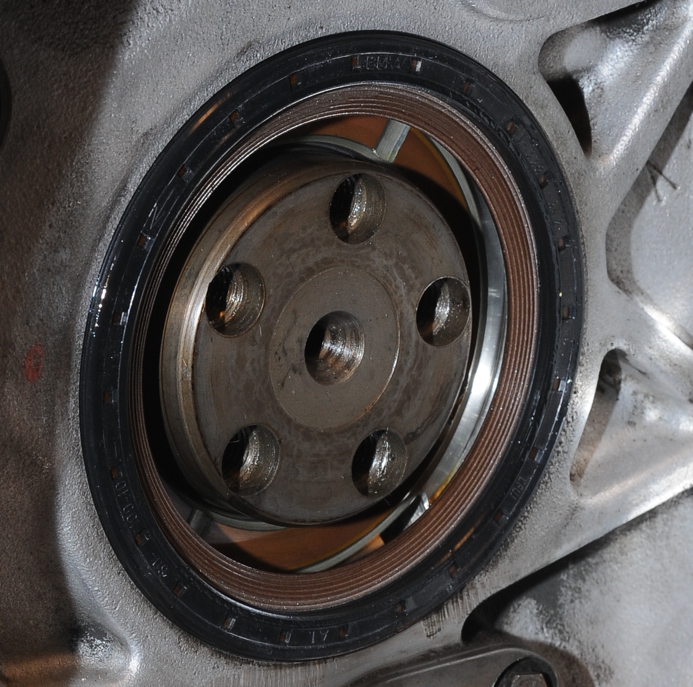
STL File: airhead-main-seal-install.zip
27mm Socket for Swing Arm Lock Nuts
To remove and install the swing arm nuts I had to modify a 27mm socket to make it thinner. The proper way to modify the socket is with a metal lathe. I don’t have one of those, so I used a Dremel tool with a grinding bit as shown here. The socket is an impact socket from my Harbor Freight socket set. I think you can buy them individually for less than $5 at HF, so I’ll throw this one in the BMW tools bin after I buy a replacement.
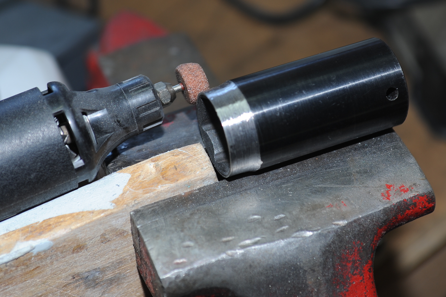 To make the grind, I would spin the socket with the palm of my right hand. I held the Dremel tool with my left hand, applying pressure when the socket was spinning, and removing pressure as I ran out of palm. It wasn’t fast, but accuracy was surprisingly good. The wood block is there to provide a stop for the socket to rub against while turning, preventing left-right movement. Don’t forget to wear eye protection!
One thing I didn’t do, but I probably should have, is to grind off the end to get rid of the bevels the way they do with this $21 socket from OCD Machine. That said, I didn’t have any problems with the socket as shown in the picture.
10mm offset adapter for drive-shaft bolts
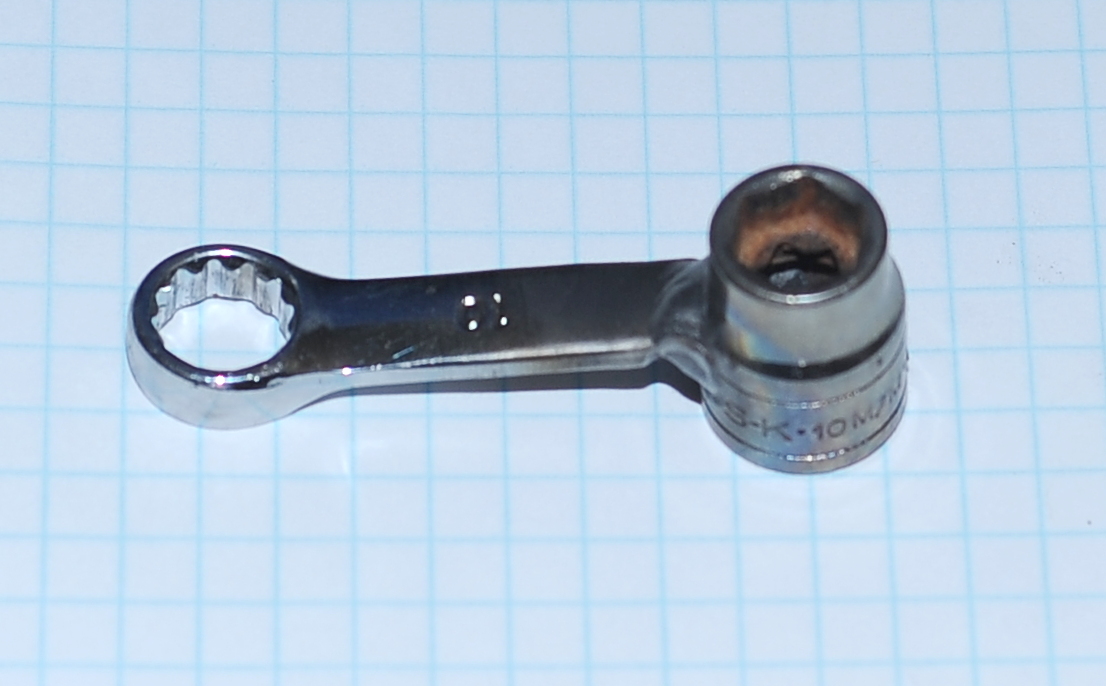
Torquing the drive shaft bolts requires a 10mm offset socket. You can buy these from Snap-On, or other places that sell airhead parts. Even though I’m a complete novice when it comes to welding, I managed to weld up a usable tool using an old socket and wrench. The only mistake I made was not making sure that the 3/8 in drive (which you can’t see) was square to the wrench. This isn’t a problem with a ratchet-style torque wrench, but with a beam-style wrench, I can’t get the adapter at either 0 or 90 degrees to the wrench.
Center Stand Tab Straightener
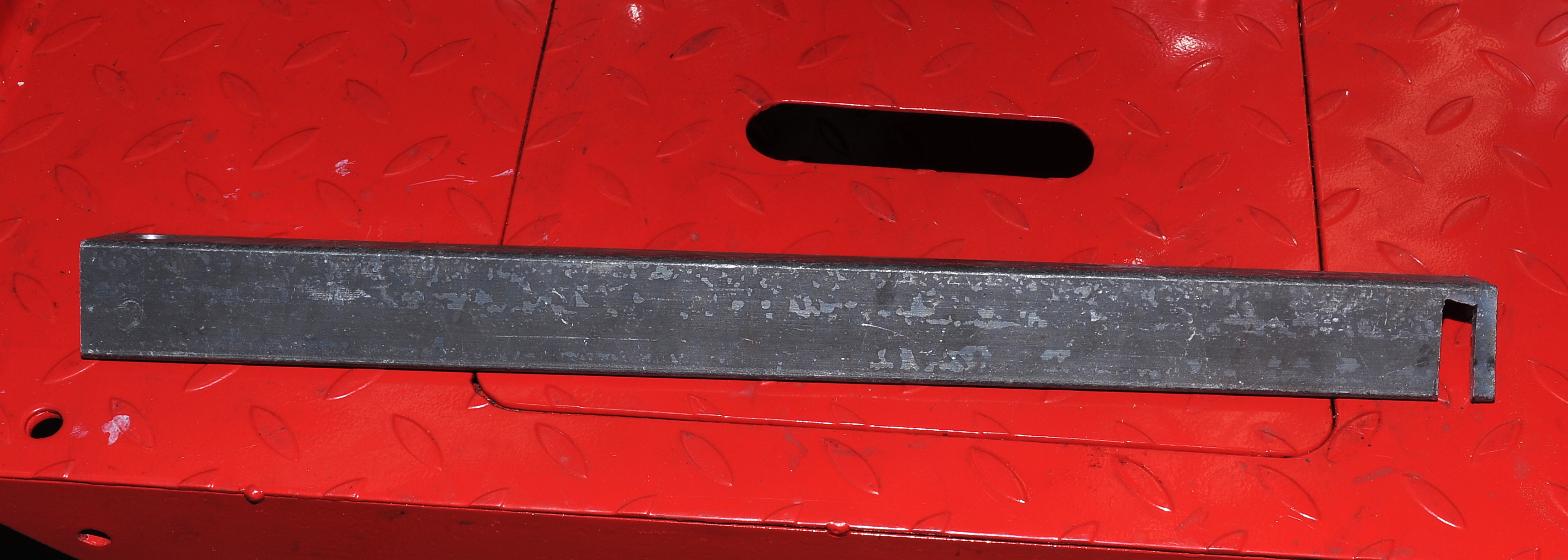
The left-side center stand mounting tab bent when the right-side bolt fell out. To straighten the tab without removing the engine I built this tool . As the front of the tab was bent in towards the engine, when I pry on the tab with this tool, all of the pulling pressure is in the upper-right corner of the notch, so that thin tab of metal didn’t need to be reinforced. The notch would need to be on the other end of the angle iron for straightening the right-side tab.
To mark the notch location I positioned the angle iron under the mounting tab and against the engine. I then used a bare hacksaw blade, flush against each side of the tab to mark the angle iron.
Mounting the angle iron in the vice I first cut the sides of the tab by hand with a hack saw and then used a plasma torch to cut out the end of the notch. Alternatively I could have just drilled a series of small holes and busted it out.
DIY Bag Pump for Air Mattress/Sleeping Pad
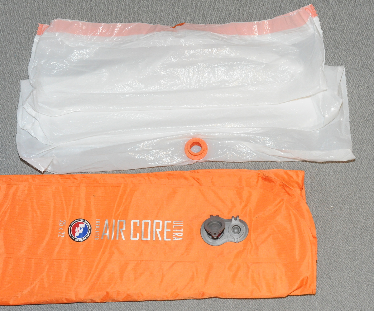
The Big Agnes Air Core Ultra insulated sleeping pad that I bough for motorcycle camping is great. However, as it’s 3″ thick when inflated, and it’s not self inflating, it takes a lot of air to fill. Not wanting to waste space on a battery powered pump I decided to build a bag pump. The first incarnation was made from a bit of PVC plumbing and a kitchen garbage bag. That worked, sort of, but the PVC tubing kept popping out of the inlet valve, and it was hard to keep a clear air path. After the last 10-day camping trip, I decided I needed something better. This second attempt works great.
The bag pump consists of three parts: a Costco plastic kitchen garbage bag, and two 3D printed parts — a nozzle and a nut. Here’s what it looks like. Unlike the Big Agnes Pumphouse Ultra, which is a dry sack, this bag pump is compact enough to be easily stowed in the bottom of the bag that comes with the sleeping pad. I carry extra garbage bags, so I’m not concerned if this one rips, though it hasn’t yet.
To operate the pump:
-
-
- Insert the nozzle into the pad’s inlet
- Capture air in the garbage bag by blowing lightly into it, or holding it open to the wind
- Quickly close the open end (i.e. wad it up in your fist)
- Gently squeeze the trapped air into the sleeping pad.
- Repeat until the mattress is full (about 5 times)
-
To see a similar DIY pump in action watch this video. The action starts a little after the 2 minute mark.
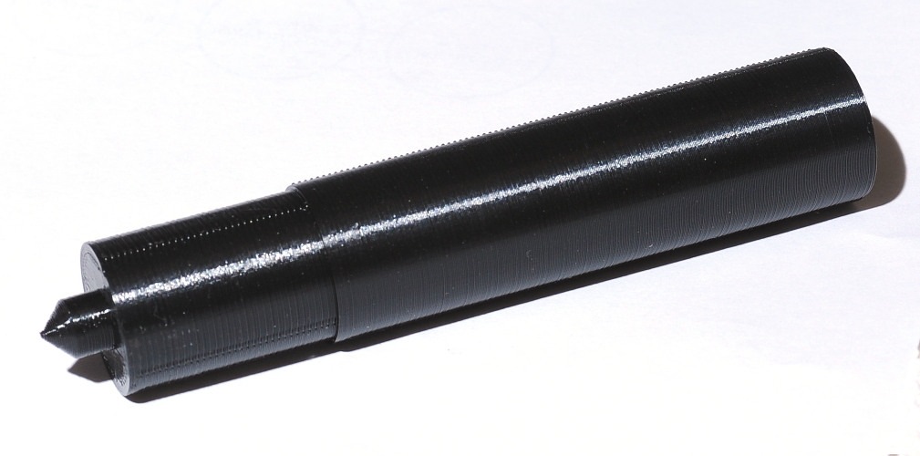
Here’s a picture of the 3D printed nozzle and nut. This is my first time printing threaded parts. The fit and finish came out nearly perfect and certainly exceeded my expectations. I admit to guessing at the clearance needed for the threads. I got lucky, they work perfectly.
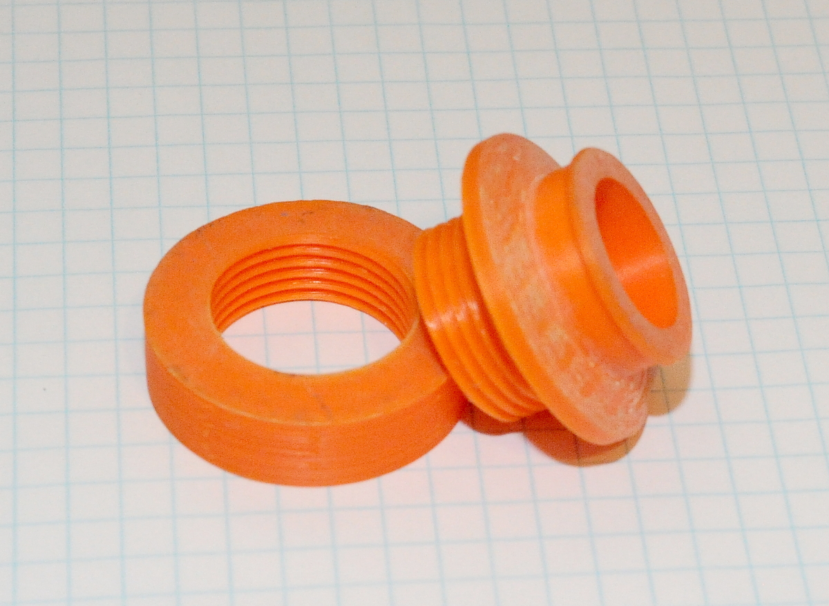
Obviously the nozzle passes through a hole cut in the bottom of the garbage bag. To cut the hole I started by turning the bag inside out and then pressed the nozzle tightly against the location I wanted to cut — stretching the plastic bag. I then cut the hole by running a razor blade around the inner circumference of the nozzle. This leaves the hole slightly undersized, which is what I wanted. After pushing the threaded end through the hole I secured everything with the nut before turning the bag right-side out.
I printed these parts using Hatchbox ABS @ 230 degrees (70deg bed) with a layer height of 0.175. The nozzle is printed oriented with the threads up. It was printed with supports for the flange. The 60 degree threads are printed without supports by limiting the supports in my slicer (Cura) to overhangs greater than 61 degrees.
While it hasn’t been a problem, the sharp edge around the nut does put a lot of stress on the plastic bag. If I ever decide to print another one of these, I think I’ll round off the sharp corners on the nut.
STL files: NozzleAndNut.zip