Removed Rear Bearing Stack

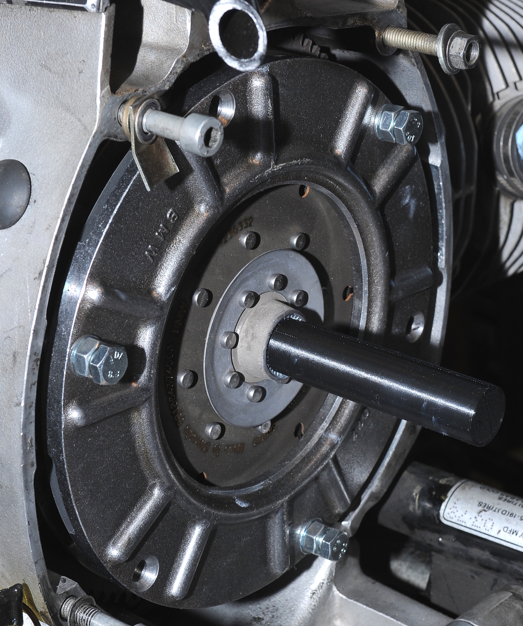
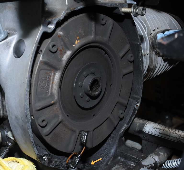
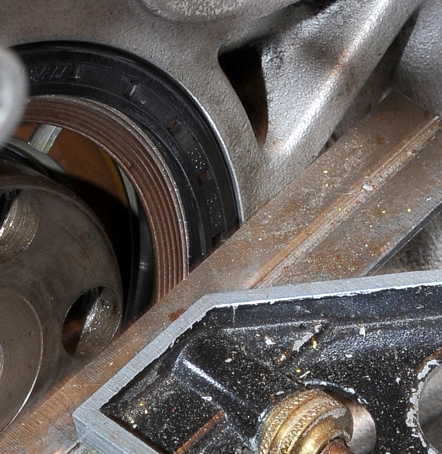
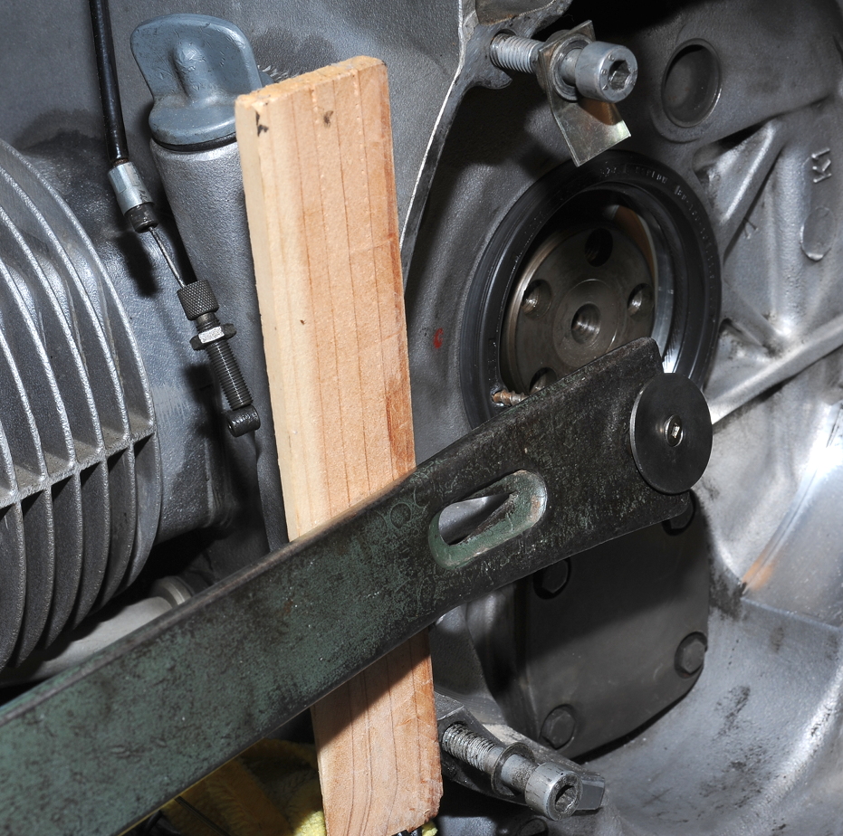
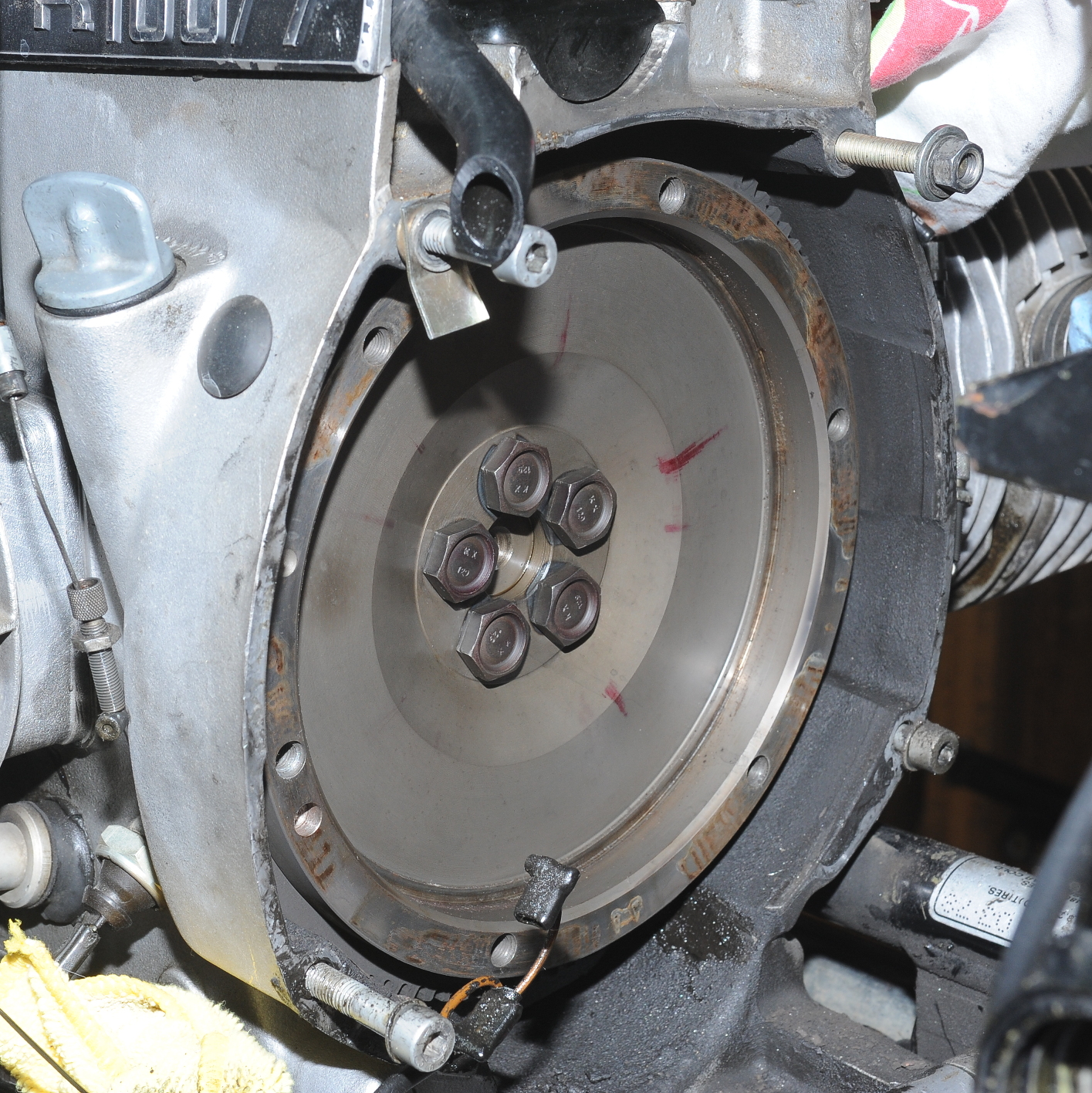
Today’s task was to remove the rear wheel bearing stack.  It took a while, but using a propane torch to heat the right side, and a heat gun to heat the left, I was finally able to get the temperature up to 225 degrees.  Unfortunately nothing was moving when I hammered on the shaft with a rubber mallet.  I began hitting a bit harder and then the whole assembly shot out on a single blow.

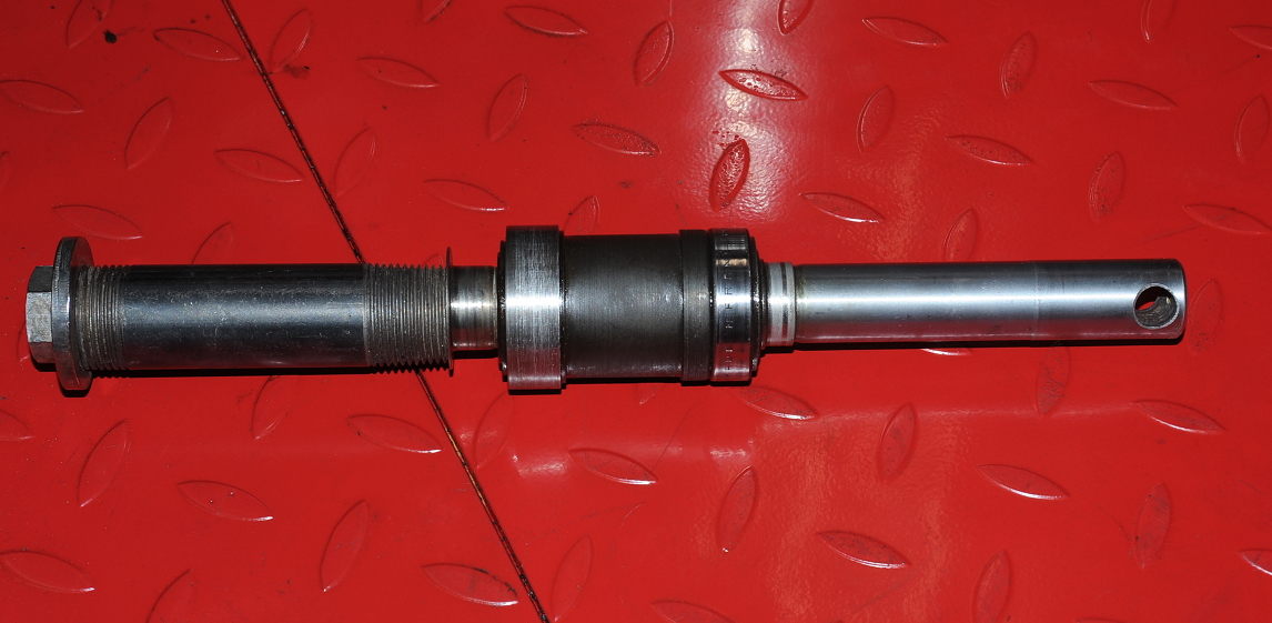
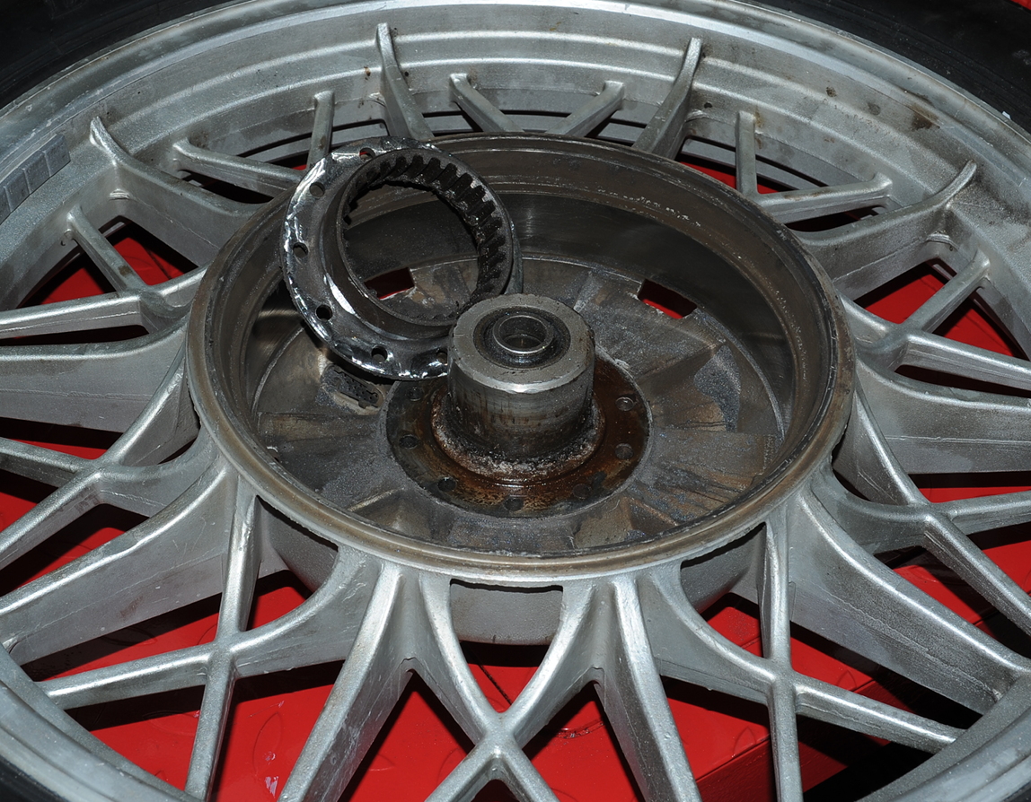
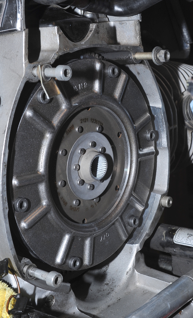
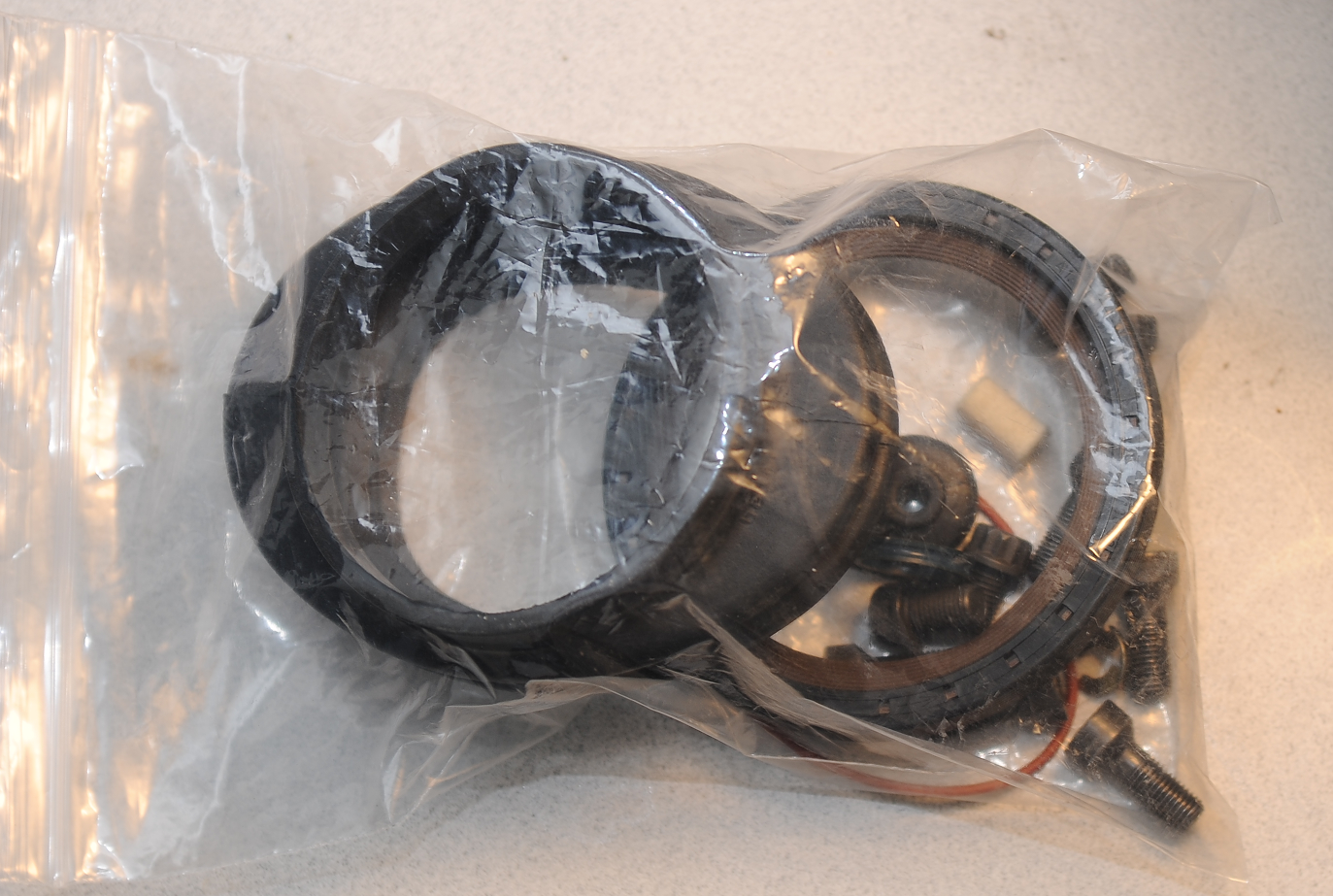
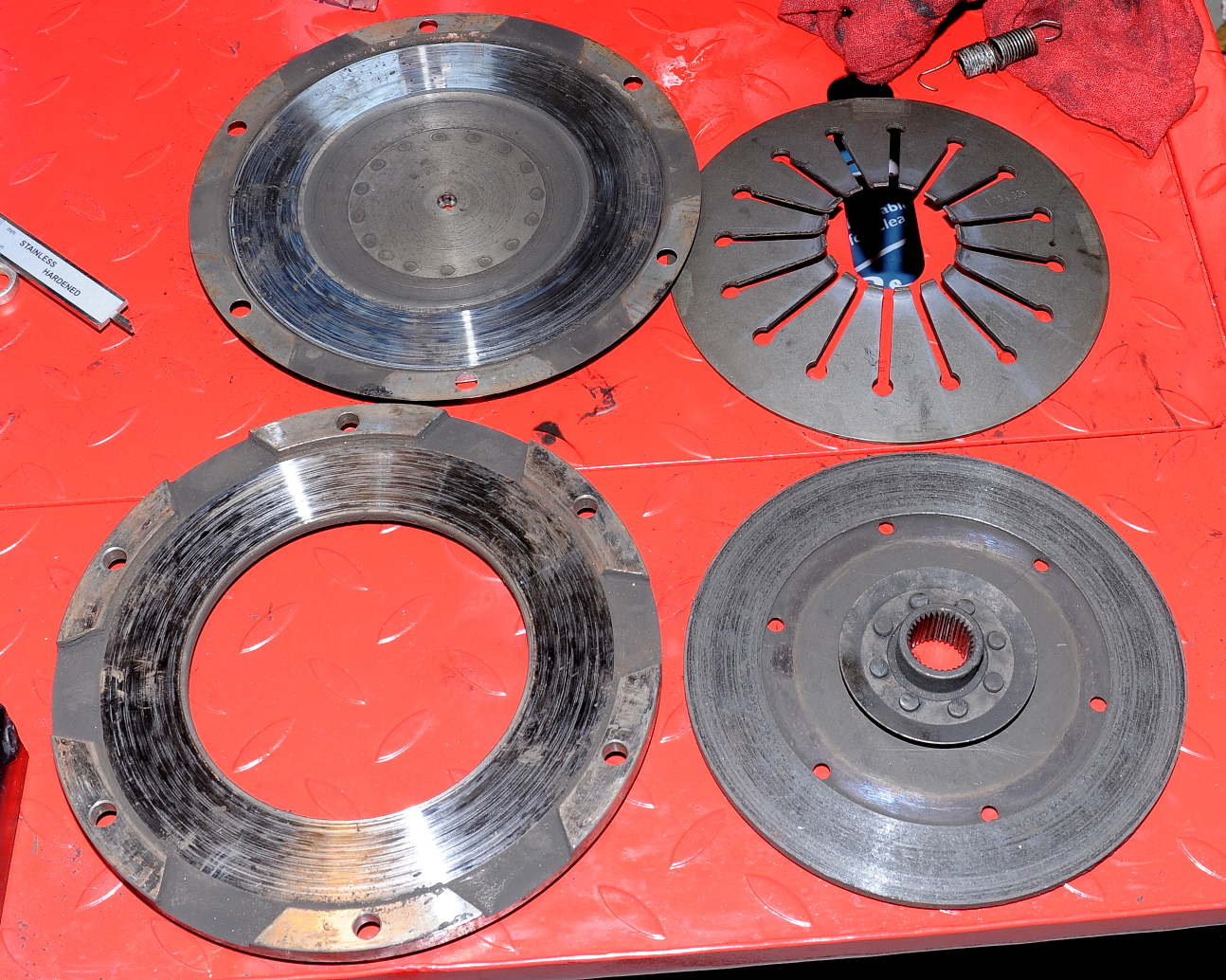
It seems that I have a bit of a hybrid hub. In picture above you can see that the bearing on the left looks larger.  That’s because there’s an unexpected steel sleeve wrapped around it.

The right bearing race fits in the aluminum hub, while the left bearing race was fitted in a steel sleeve, which was fitted in the aluminum hub.   I’m pretty sure this was a repair for spinning bearings.

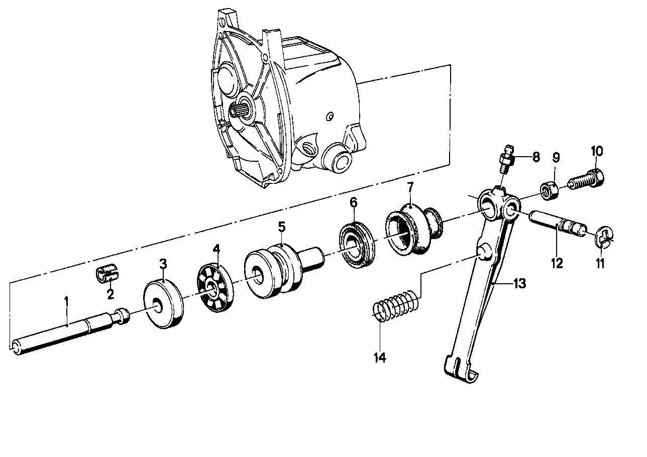
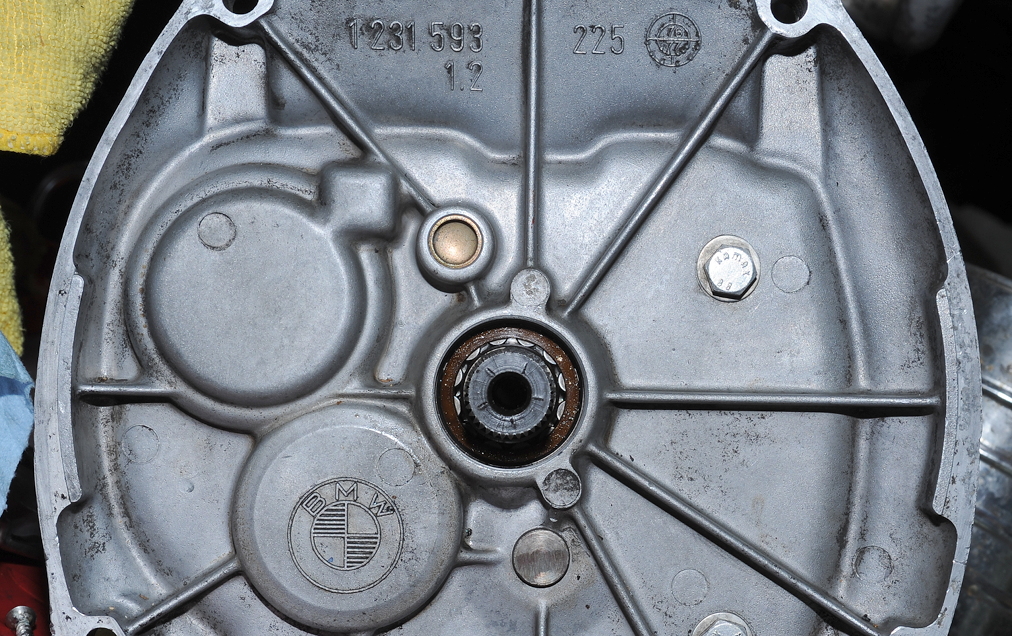
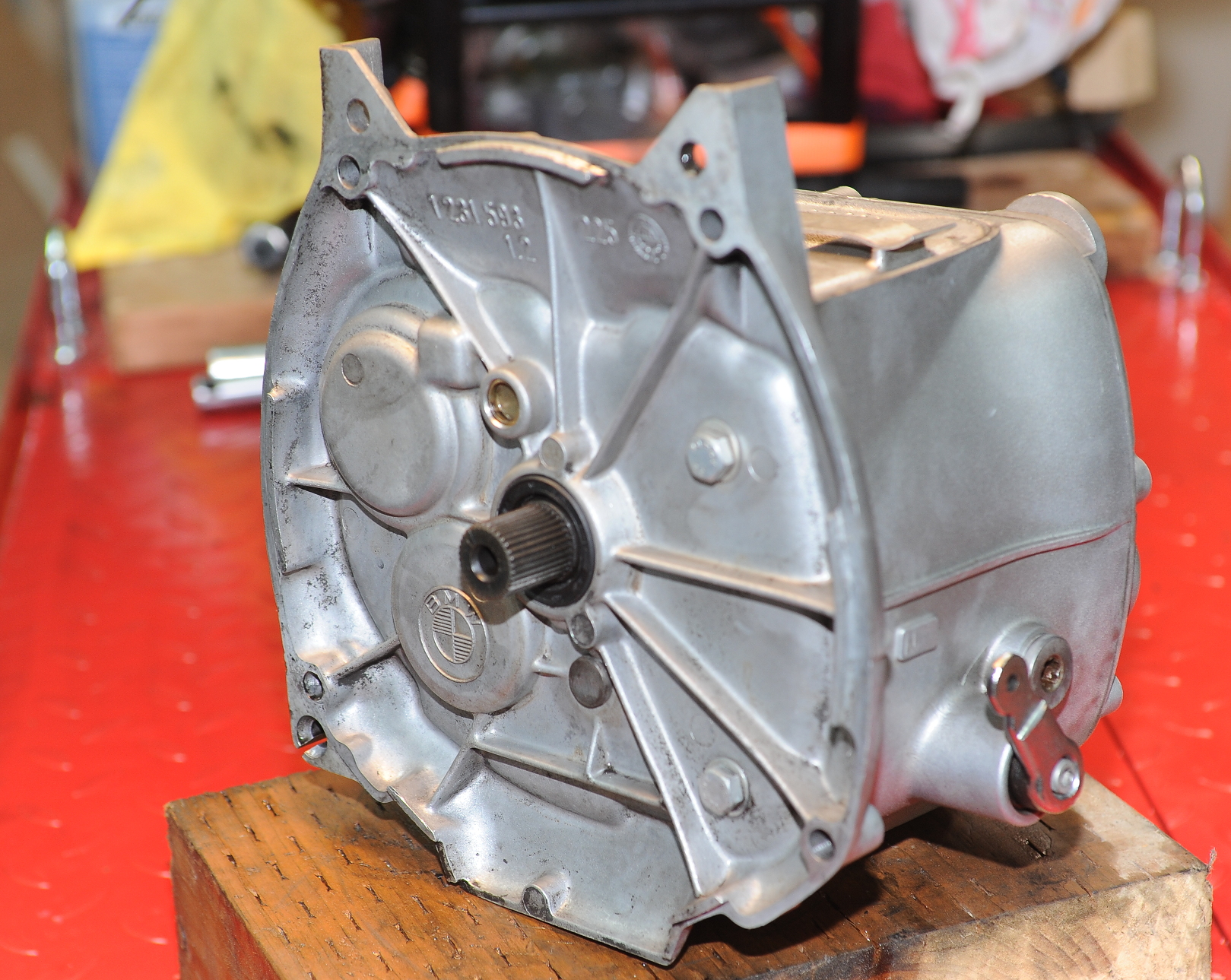
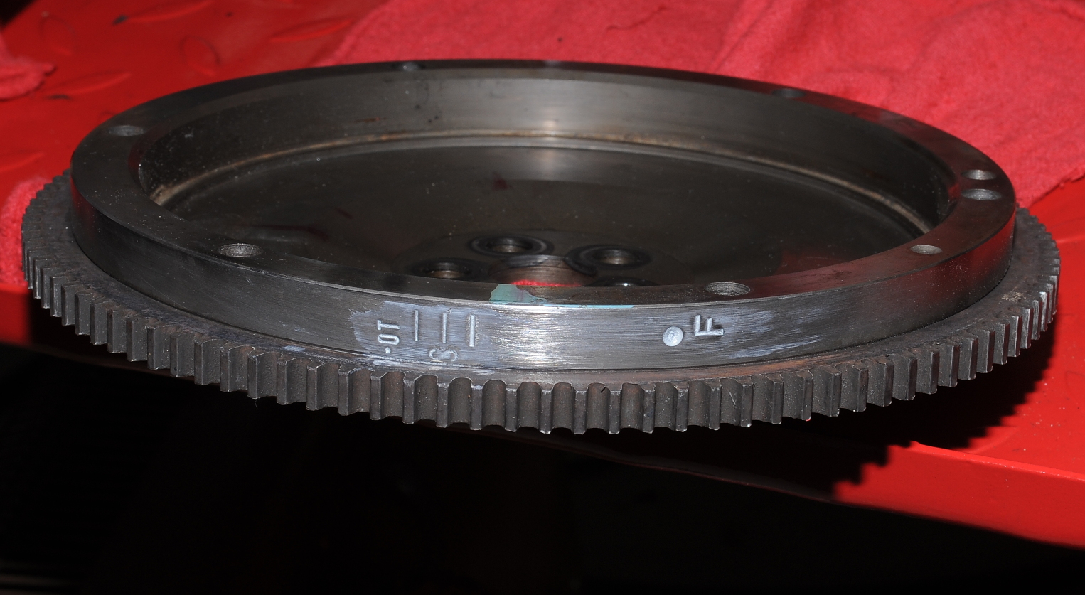
This early ’78 wheel is a bit of an oddity and was sort of a transition for BMW from spoked wheels to alloy.   This wheel uses the seals listed for the spoke wheel (35 and 36mm), not the 40mm seals shown in the parts fiche for the snowflake wheel.  By late ’78, the design had changed to use steel in the hub, eliminating the need to heat the hub to remove the bearings.

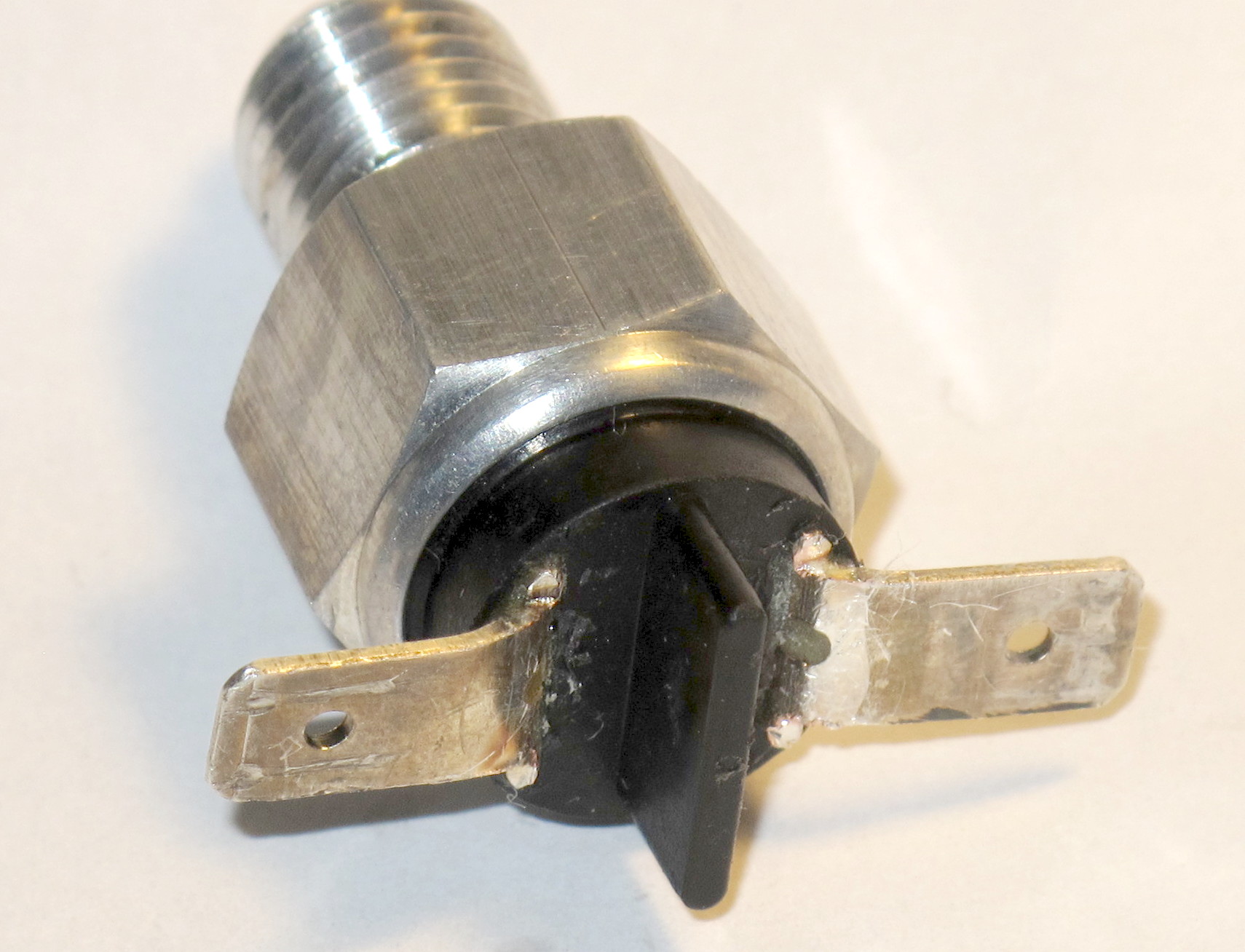
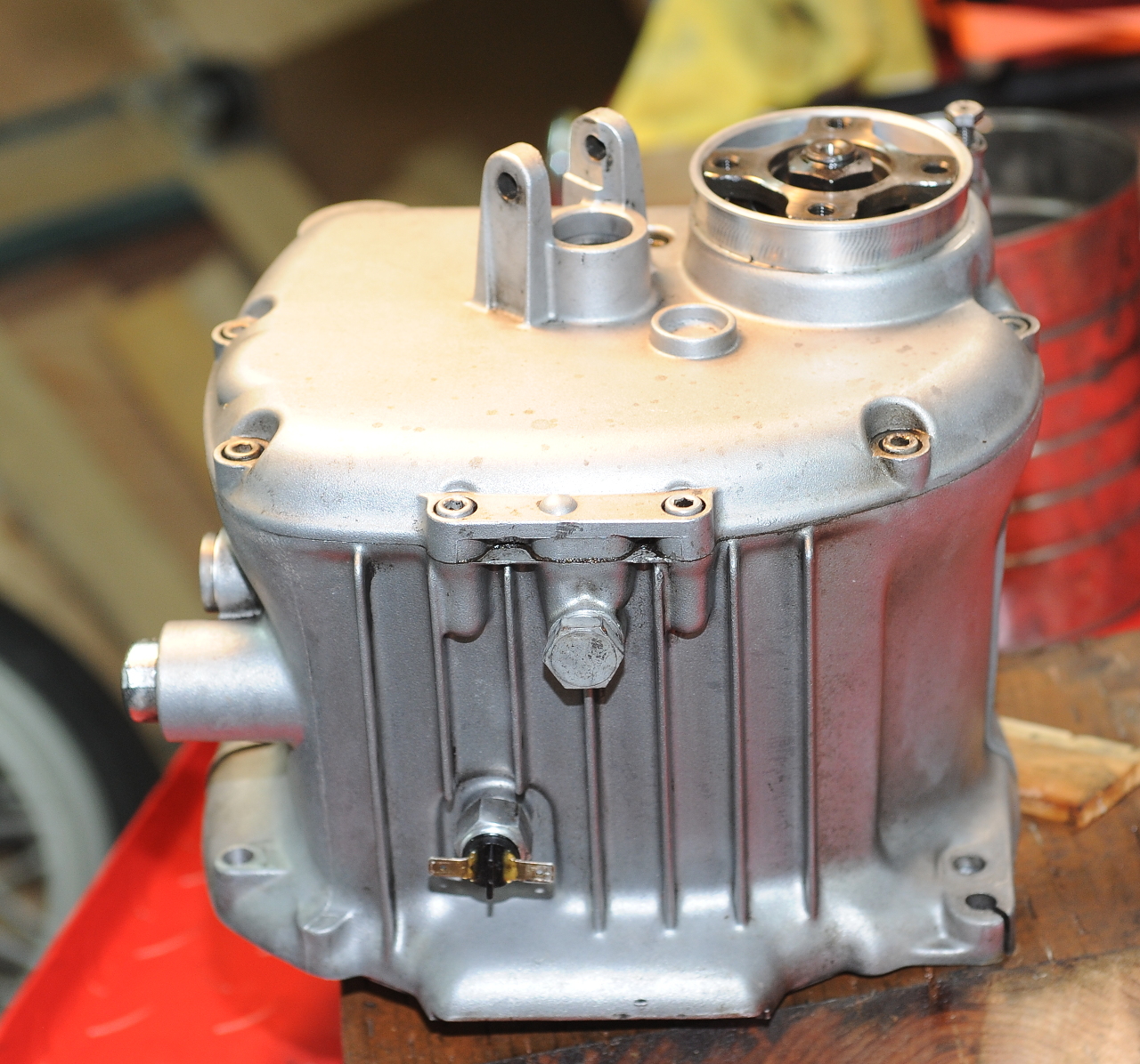
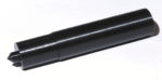
Note:  In the picture above I reversed the left top hat so that the 3/4″ schedule 40 pipe would have a flat surface to press against.

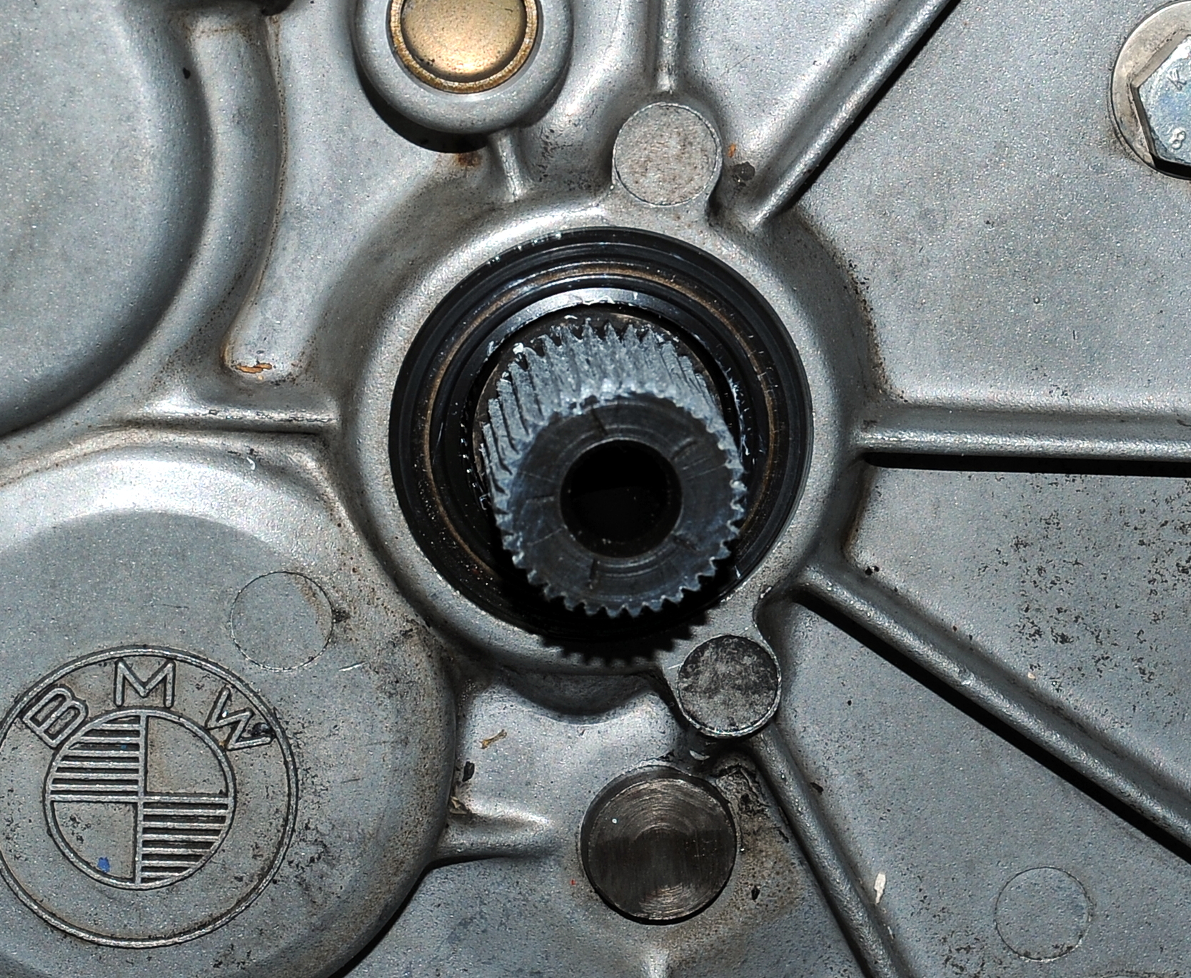
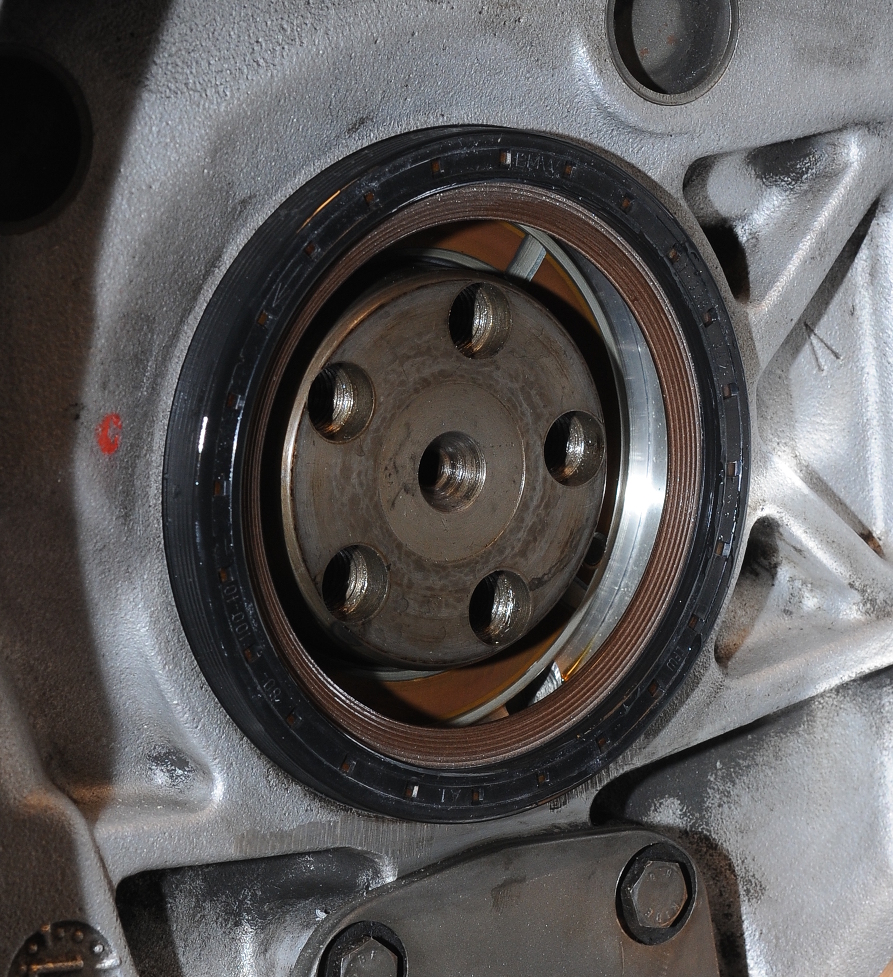
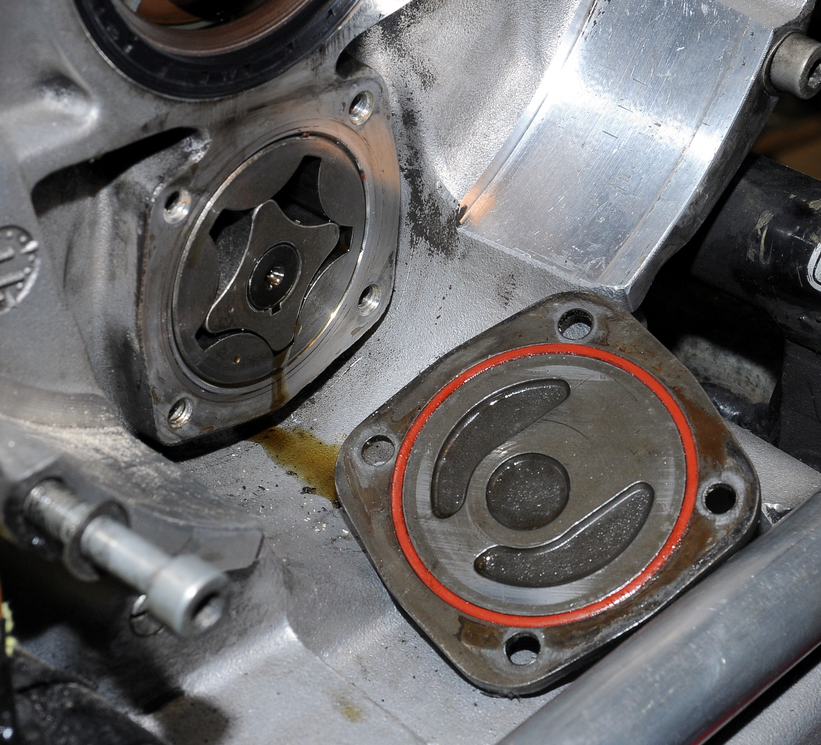
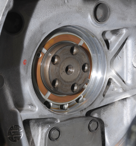
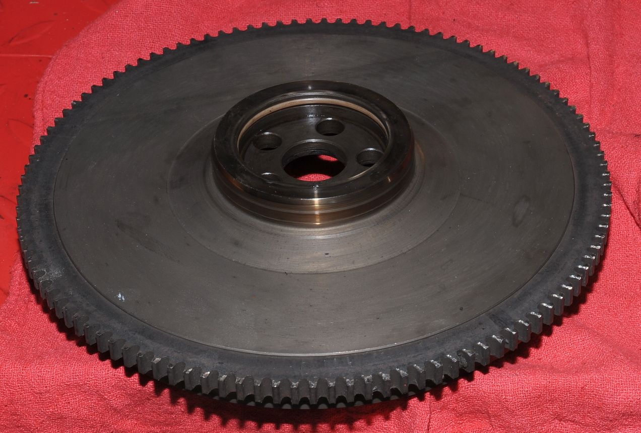
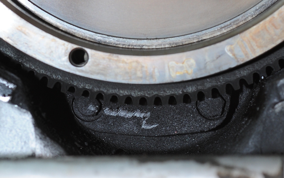
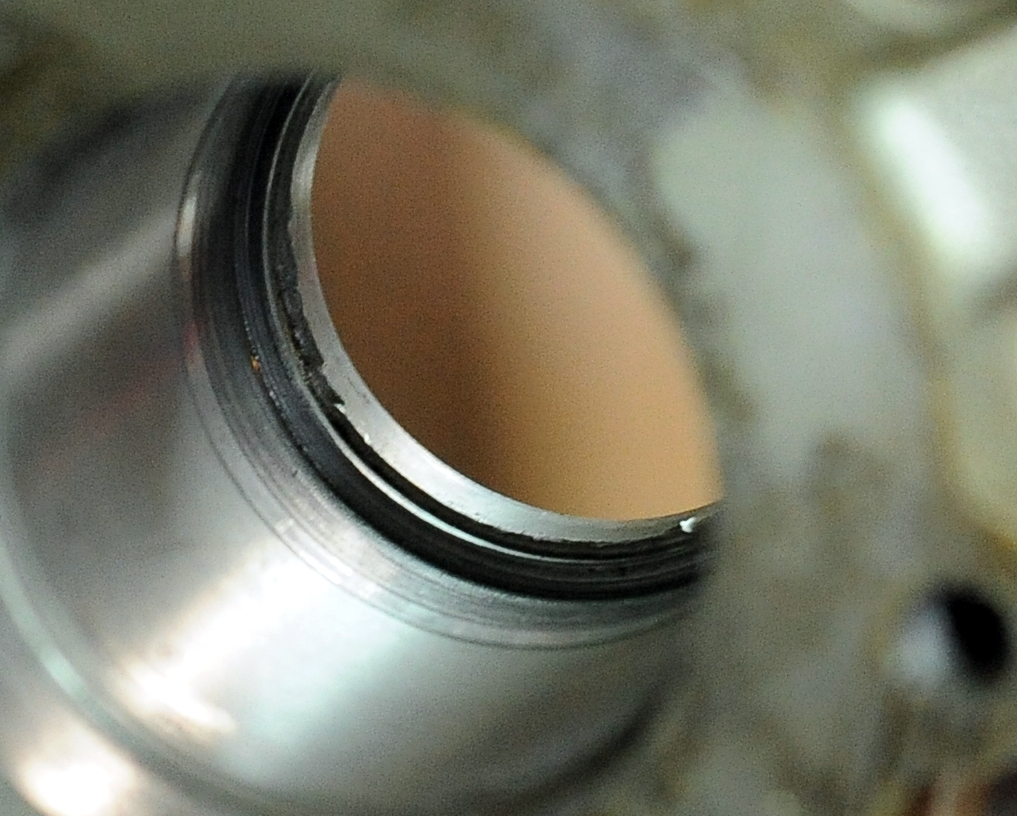
Here you can see the larger diameter section in the hub where the left bearing steel band was located.  This had to have been milled out during a repair.

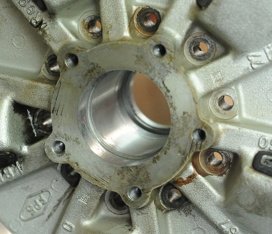
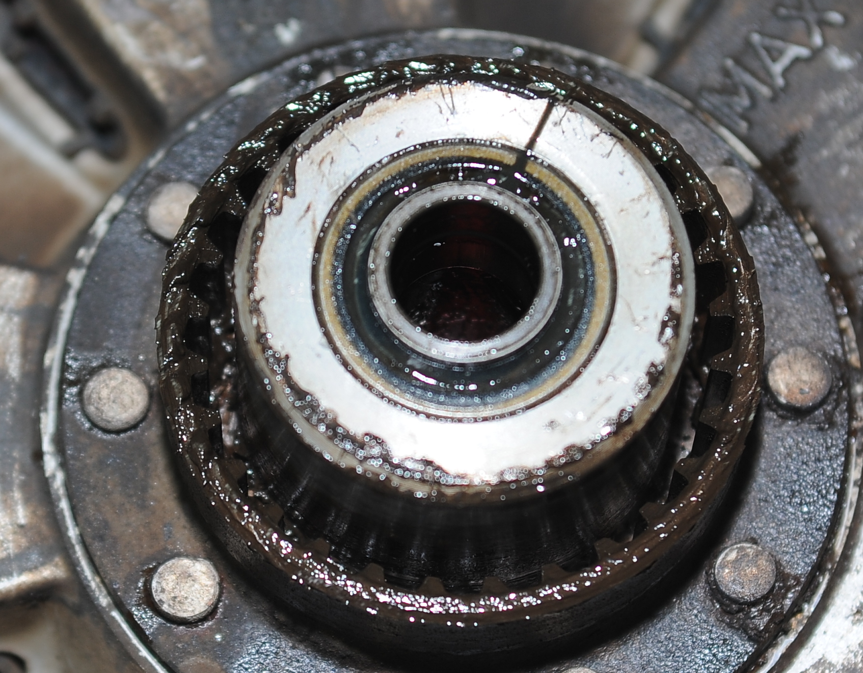
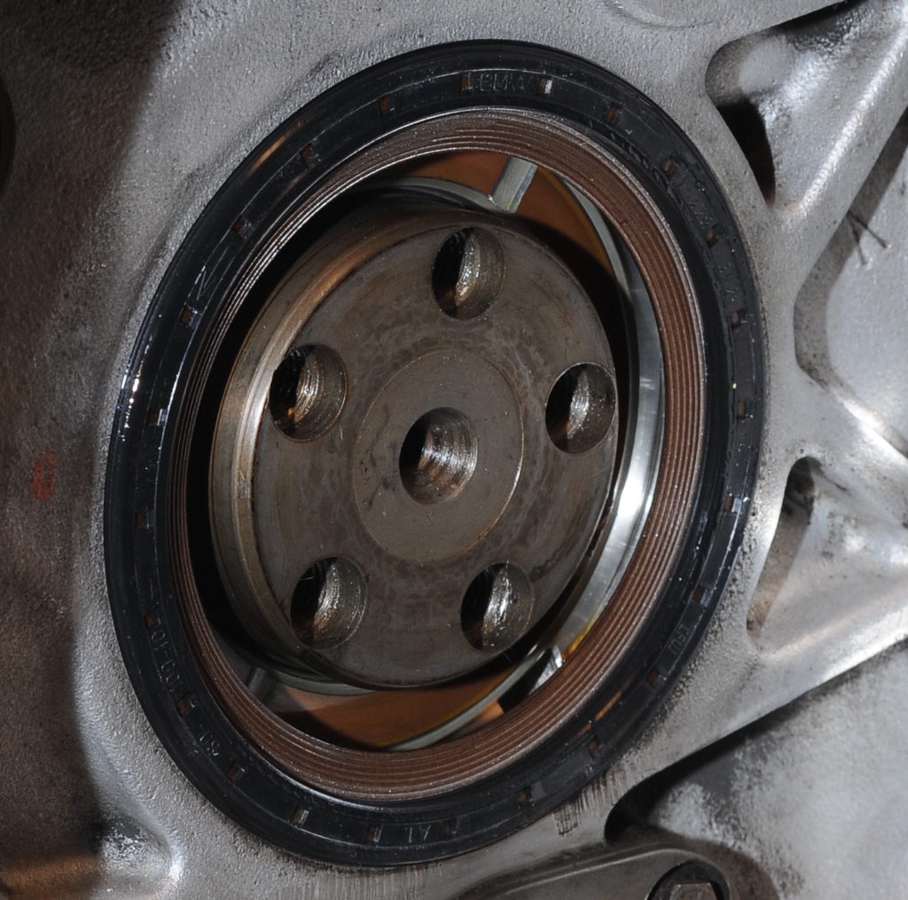
Unfortunately, the right side of the hub shows evidence of the bearing race spinning.  There’s no easy way to repair this so I’ll have to find a replacement wheel.  I thought about using Loctite 648, but that’s probably not the best way to deal with this problem.  The newer wheels have steel inserts and won’t  suffer from this problem.   As the front wheel was replaced under recall, it already has the steel inserts.

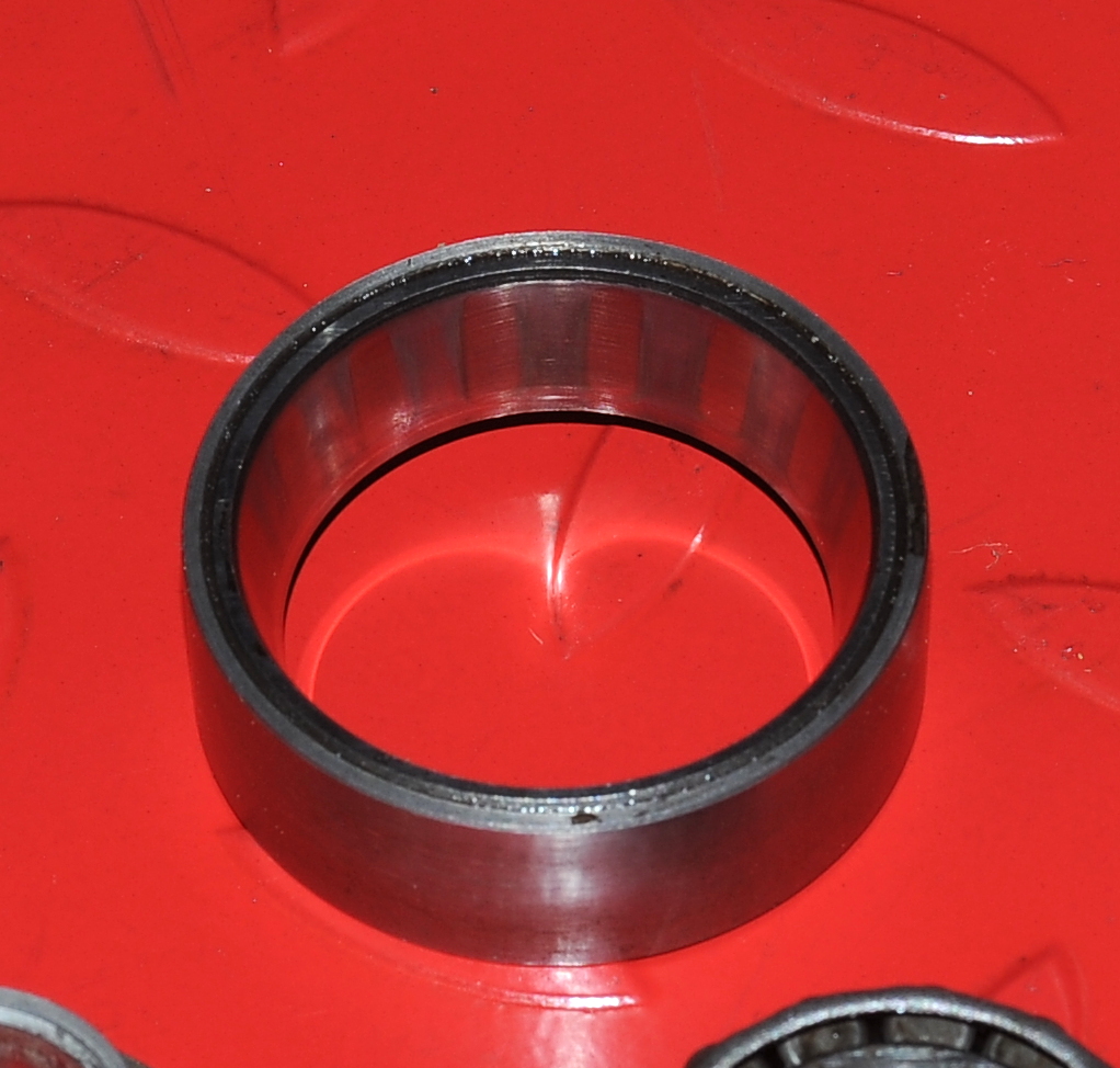
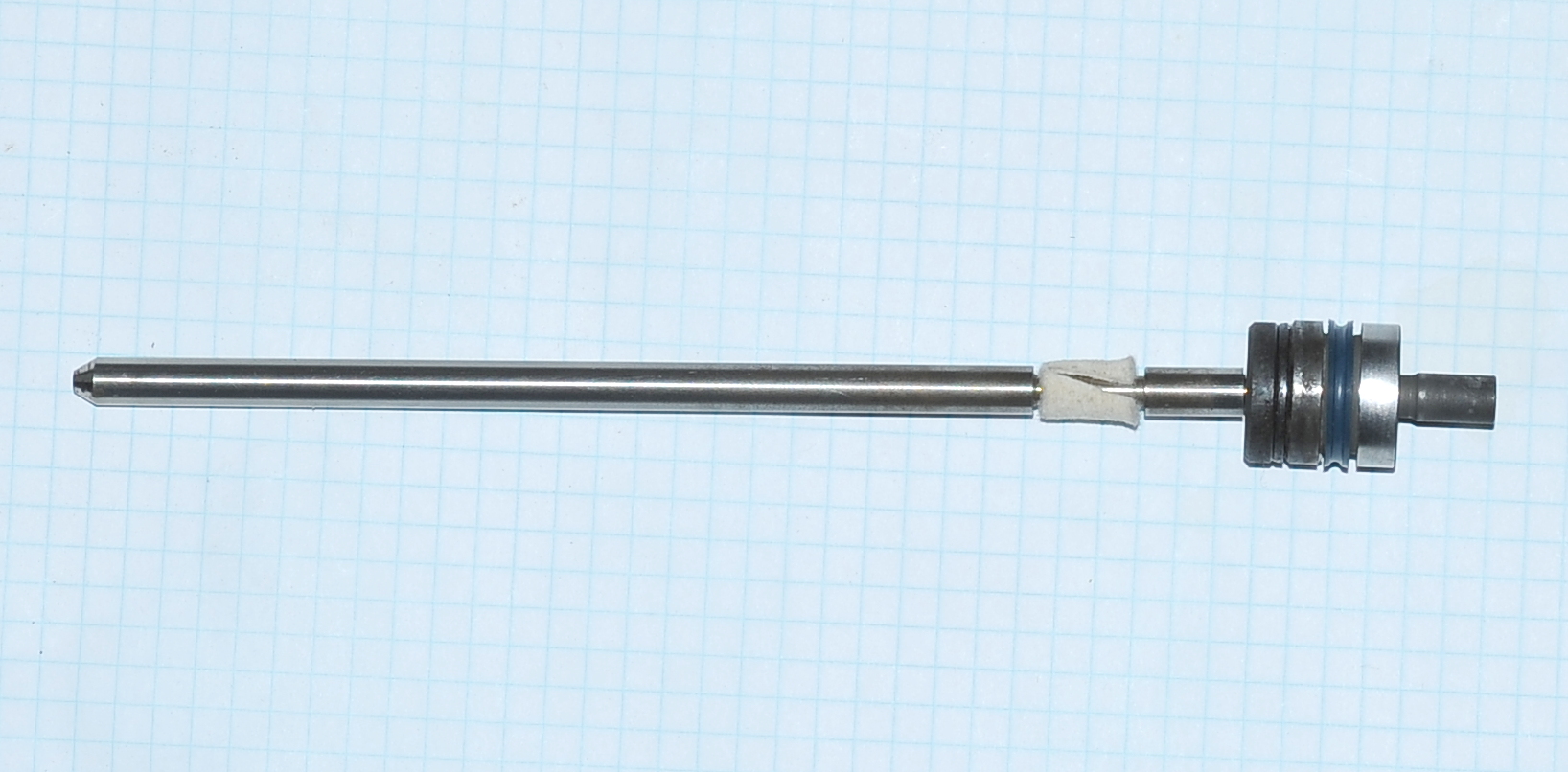
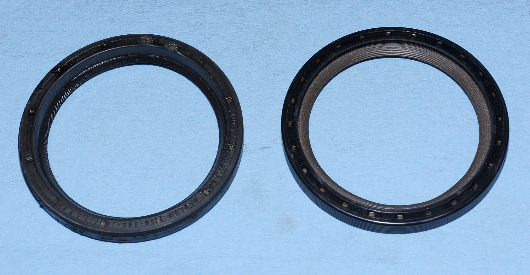
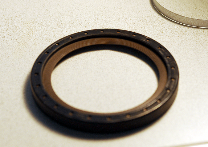
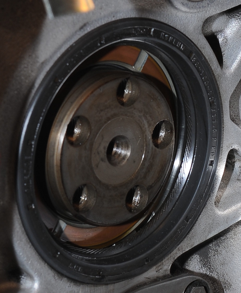
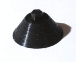
Here’s the right bearing race.  It’s showing signs of wear.  While it’s hard to tell if this bearing has spun, it does look smoother in some places around the outside than others.  Hard to tell.
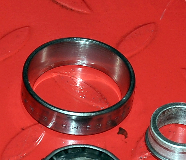
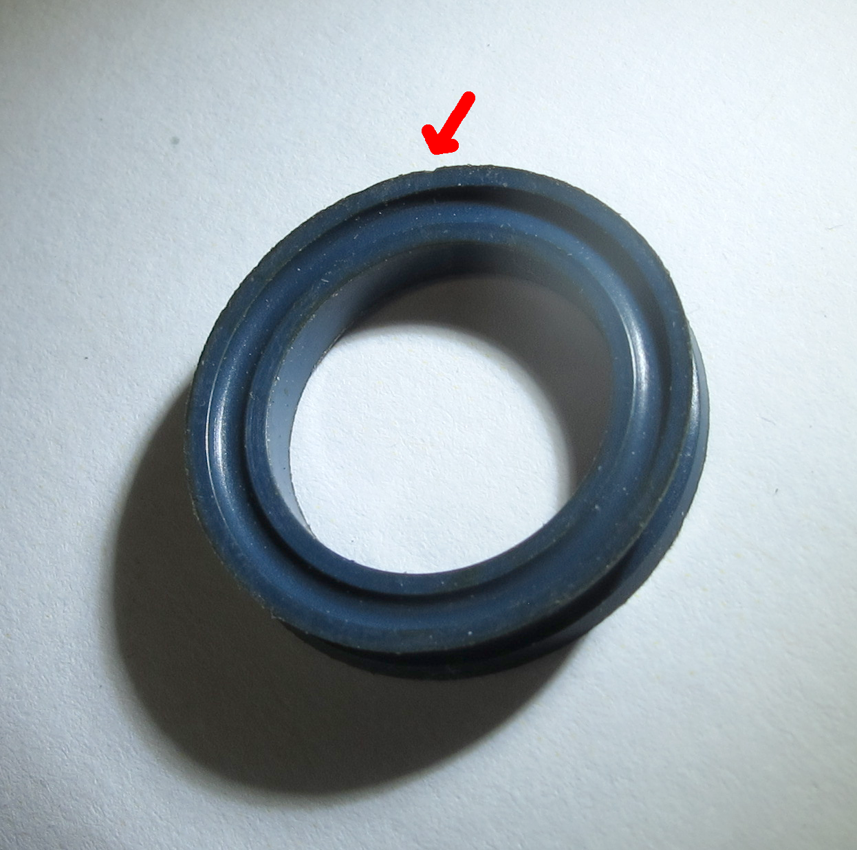
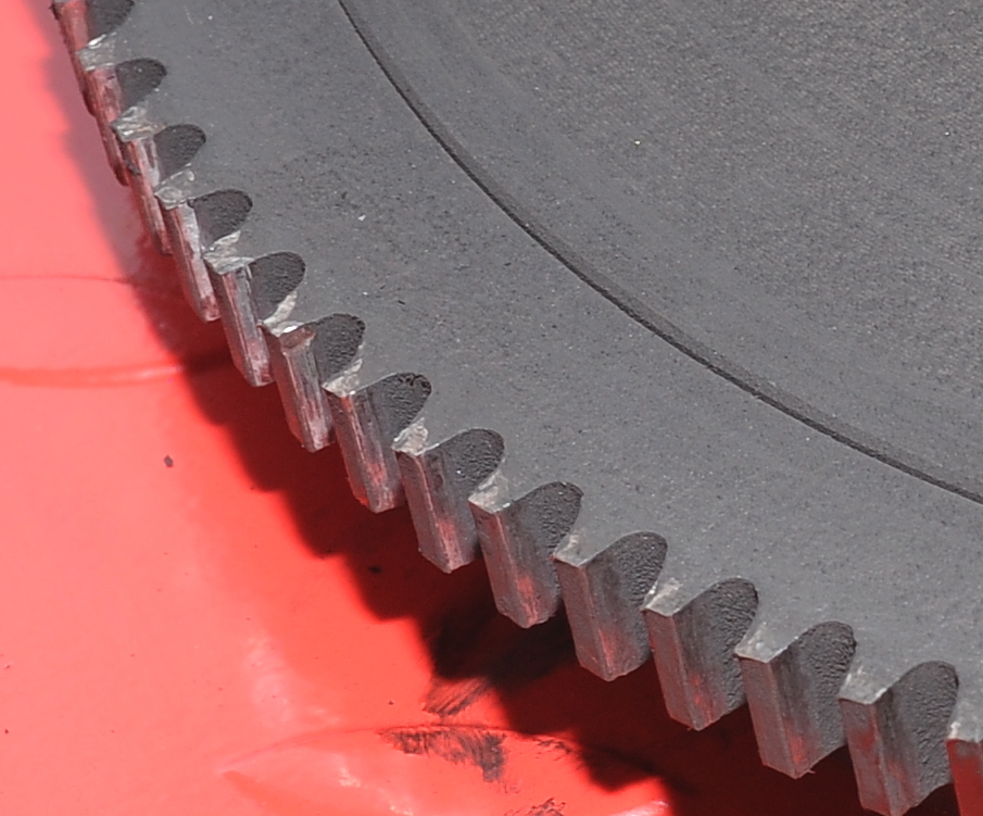
Given the brinelling, the left bearing definitely  needs to be replaced. 


Transmission: IN, Spline cup: OUT

The transmission is back in the bike and the clutch is adjusted.  I adjusted the clutch for about 2mm play at the transmission, and 3mm play on the handlebar. I still need to refill the transmission with gear oil.  You might notice that the rubber is missing from the foot peg and gear shift lever.   I have new rubber for those.

The shift lever was disassembled, cleaned and greased with NLGI2.   Same for the clutch arm.  The clutch arm also received a new rubber boot.

The clutch piston was greased with general purpose grease (non moly), same as used for the throw-out bearing.

The job of removing the spline cup was easier than expected.  When I dropped off the final drive at Hansen’s Motorcycle Shop I had a chance to chat with Craig Hansen about removing and installing the cup.  To remove the cup, they use a chisel and just knock the heads off the rivets.  I tried that, but couldn’t make it work.  The chisel, hammer, or perhaps me, was just to wimpy.

What did work was to use an abrasive cutoff wheel in my Dremel tool to cut all around the edges of the rivets, but not quite all of the way through.  Then I used a chisel to finish the job.  Before driving the rivets through I used a grinding stone in the Dremel tool to make sure that the riviets were flush with the spline cup.  That was done to ensure that the rivets were round and wouldn’t damage the wheel as I drove them out with a small punch.

In this picture you can just see the lip in the hub that keeps the spline cup centered (click to enlarge).

Here’s the before picture showing the rivets holding the spline cup.  It was easy to cut most of the way around each rivet with the abrasive cutoff wheel.  Since I was replacing the spline cup, I didn’t care what damage I might cause to it.    Before deciding to do this with a Dremel tool  I thought about grinding the heads off with a 4.5″ abrasive disk.   However, I was worried about accidentally damaging the rim.  The smaller Dremel tool was easy to control and the whole job took about 30 minutes, max.

Now the question is whether to use bolts or rivets when installing the new cup.  Bolts I can do myself.  Rivets I would have to have someone else do.  Craig Hansen said that most of the problems they have seen occurred with bolts.

Neutral Switch Repair, Transmission Input Seal and Clutch Push Rod Assembly

Before installing the transmission I had to address the problem of the oil-leaking neutral switch.   This is an apparently common problem, even with new switches.  As this switch otherwise seems to work, I’ve attempted to seal it with JB Weld.

There seems to be many variations of switches used on airheads, so the first step is to document this switch so that I know what to buy should I ever need to replace it.

First, it’s normally closed (NC).  That is, the switch conducts when the plunger is not depressed.

The washer is 1.8mm thick, as shown here.  Its inner diameter is ~12.4.  The outer diameter is ~19.9mm.

The switch length from the shoulder to the tip is 19.5mm. 

It appears that someone’s already added sealant to the connectors.

Upon closer inspection, it also appears that the original repair has failed.  The sealant has separated from the back side of the connector, and also cracked at the bend.  Before seeing the damage, I was tempted to leave the original repair in place. 

All cleaned up, degreased and after a bit of sanding to roughen things up, ready for epoxy.  Using a sharp chisel and a microscope, it was easy to remove the old sealant, whatever it was, without damaging the switch.  The connectors are very clean in most places under the old sealant suggesting the sealant was added when the switch was new (so probably not the switch installed at the factory).

I used JB Weld Original to seal the switch.  I first tried RTV, but it shrank while curing and pulled away from the connectors.  Others have used JB Weld, so I expect this repair to hold.  You’ll no-doubt notice that I’ve sealed not only the connectors, but the crimp joint as well.  Oil kept seeping out of that joint while the switch out of the transmission, so I suspect it was the primary source of the oil leak.  Using a toothpick  I tried to force as much epoxy as I could into the joint.  All of the remaining plastic was coated with JB Weld, just for appearance sake.

The new transmission input shaft seal went in easily.  I didn’t need to make an install tool as I was able to use a 30mm deep socket to drive the seal in.   Before installing the seal, I coated it in transmission oil and wrapped electrical tape around the splines to protect the seal as it was being installed.  After removing the tape, the shaft splines were lubricated with Staburags NBU30PTM, just like on the clutch disk.

A little bit of the Staburags grease will also be used on the tip of the clutch push rod.  Here’s the entire push-rod assembly with the new felt seal, lightly greased throwout bearing and a new piston seal (blue).   It took some time to get the rod inserted as the new felt seal would expand and find things to catch on.

The needle bearing is serviceable but should probably be replaced the next time the transmission is pulled.

For reference, the picture above contains parts 1-6 in the drawing below.

The drawing appears to be incorrect with regards to the rubber boot (7).  The narrow end goes over the end of the piston (5) while the wide end fits over a groove in the arm (13).  That seems to be the way it should go together, and here’s what it looked like before I took everything apart.  I have a new boot to install as the old one was split.

The grease fitting only seems to service the shaft, so I’ll be putting a bit of moly grease where the adjustment bolt (10) pushes against the piston (5).

As soon as the JB Weld cures, the transmission can be installed.

Installed Oil Pump Cover, Flywheel and Clutch. Removed input seal on transmission

The new flywheel bolts finally arrived so it’s time to start putting stuff back together.

I started by installing the oil pump cover, using medium blue Loctite on the bolts.   I then installed the flywheel and torqued the bolts to 77 ft-lbs.

The clutch spring was lightly lubricated with Staburags NBU30PTM grease around the outer edge and on the ends of the fingers.   Here  you can see my 3D printed clutch tool being used to align the disk.  There’s not a lot of pressure as the three temporary long bolts are holding the assembly in place, so it’s easy to move the disk into alignment.

I couldn’t find any balance marks, so I assumed the parts had been dynamically balanced at the factory.

With the disk aligned I fully compressed the spring using the nuts on the long bolts and then installed the new clutch bolts torqued to 210 in-lb (17 ft-lbs).  You can also see the light coating of (white) Staburags grease I used on the splines.Looks better than before!

I also removed the transmission input shaft seal.  It was a real pain to get out, and it didn’t come out in one piece.  In this picture you can see the roller bearings around the input shaft.  Tomorrow I’ll install the new seal.

Rear Main Seal and Oil Pump

Tonight I installed a new rear main seal and oil pump cover gasket.

To install the new rear main seal, I lubricated the seal with a bit of oil and then set it in place.

The 3D printed seal install tool was then put in place.   Here I have the flat side out just so that I can demonstrate installing the seal that will sit proud by 2mm.  The old flywheel bolts were first hand tightened and then tightened using a socket wrench.  I tightened each bolt in turn 1/4 turn until the plastic bottomed out on the case.   Here you can see I installed washers, but honestly, there’s so little pressure, you don’t really need them.    You also don’t need to tighten in a cross pattern.

Here’s the seal installed with the same height above the case as the old style seal that I pulled out.

I turned the tool over so the flat side was against the seal and tightened again until the plastic was against the case.  Now the seal is flush.

Before installing the flywheel I wanted to replace the oil pump cover gasket.  While I had the cover off I measured the outer rotor to case clearance at 0.005″ The spec is 0.005″ to 0.008″, so that’s good.  I also attempted to measure the inner rotor tip clearance, but the thinnest gauge I have, which is .0015″ wouldn’t fit.  So the clearance is less than .0015″.  This spec is .001 to .003, so again all is good.

For reference, the cover installs with the indentations oriented towards the bottom as shown.  This picture was taken just after the cover was removed and before the seal was replaced.

Cleaning the transmission while waiting for parts

As I’m still waiting for a few parts to arrive before putting everything back together (minus the final drive) I decided to clean up the transmission tonight.  One of the parts I’m waiting for is the input shaft seal.  I’m also waiting for new flywheel bolts.

The transmission looks a lot better now!  The black seal around the splined input shaft is the one that will be replaced, along with the main rear seal on the crankshaft, the felt seal on the clutch pushrod and seal on the pushrod piston.  I hope that solves all of the leaking problems!

The transmission oil has been drained, so I’m going to pull the neutral switch and see if I can seal the switch with epoxy, something similar to what’s described here.

Most if this clutch dust and oil cleaned up easily with brake cleaner and/or kerosene.  For some reason the bottom center section was hard to clean, the crud didn’t want to dissolve.

Removing the Rear Main Seal

The rear main seal is out.  Removing it wasn’t too difficult.

Here’s a side-by-side of the old seal (left) and the new teflon seal.   They’re both exactly the same size, though the teflon seal is supposed to be installed flush.  The seals are 100mm in diameter and 10mm high.   All of the pictures in this blog are high resolution, click on the picture for higher resolution.


To remove the old seal I drilled a hole in the seal at 9 o’clock and inserted a drywall screw with a fender washer on the end.  It was a longer drywall screw,  the screw head needed to be about the same height as the edge of the case.   I also drilled slowly, and inserted a rag to keep the metal filings from flying into the engine.  While the seal is rubber (or plastic) on the outside, I was drilling into metal.

I didn’t have a slide hammer or fancy seal puller, but I did have a small wonder bar (flat pry bar).  I placed a block of wood on the edge of the engine case to use as a fulcrum.  While applying pressure to the pry bar, I tapped on it with a hammer — not too hard.  The seal slowly began to rise and then quickly came out.

Unfortunately I won’t be installing the new seal into the engine today.  The dealer I bought this from shipped all of the parts as shown in this next photo. All of the seals were in the same bag as sharp-edged objects such as drive-shaft boot clamps (not visible) clips, clutch bolts and drive-shaft bolts.  They were also subject to the weight of the clutch components sliding around in the same box.

The dealer is supposed to be sending me a new seals ASAP.  I don’t want to risk using these unless I’m forced to.

The main seal was deformed when I pulled it out of the bag as shown in the next picture at 12 o’clock.  Now this teflon is flexible, and generally tough, but that’s not the point.  The seal could have been over-extended and there may be small scratches that accelerate wear.  It just sad that the person doing the packing couldn’t take the time to protect these expensive parts from damage during shipping.  

The clutch seal (for clutch rod piston) had a couple of notches taken out of the edges (red arrow for one).   I can’t be sure that this damage happened during shipping, but with the part in the bag with lots of sharp-edged products, there’s every possibility that it did.   

Pulling the flywheel

The flywheel is out.  As you can see, things are very dirty, but the rear main seal, if leaking at all, is leaking very slowly.   The new seal is on its way, so I’ll probably install it anyway.  The new seals are supposed to fit flush with the case.  This one sits proud by about 2mm.  I’ve also ordered a new seal for the oil pump cover at the bottom.

Looking much better after cleaning.  Notice the ’77 date stamp in the lower, left corner.

Here’s a closeup of the rear main seal.

The flywheel is in very good condition.  You can see some minor wear on the teeth, still, not bad for 75k miles.

The main seal seals against the center hub.  The hub is discolored, but is very smooth — nothing rough or sharp to damage the seal.

The timing marks will show up a little better with some white paint.  The OT mark is top-dead center.

Next up is cleaning up the transmission and,  after I receive all of the new parts, main seal and flywheel installation.

3D Printed Airhead Tools

It turns out that plastic tools are perfectly fine for some tasks.  With the advent of low-cost 3d printers I think it makes sense to explore 3D printing as a way of fabricating specialized tools for our airheads.

So far I’ve built two tools: a clutch alignment tool, and a tool to keep the crank in place while removing the flywheel.   For more information about these tools, including the STL files visit my tools page.

Clutch Alignment Tool
Tool to keep crankshaft from moving when working on the flywheel

The next tool I hope to design is a rear-main seal installation tool.

Pulling the clutch

If you’re interested in how this clutch works, visit my tutorial Airhead Clutches Explained .

To remove the clutch I needed three long 8mm fine-thread bolts, nuts, and washers so that I could release the pressure without damaging anything.  After a quick trip to Ace Hardware I was in business.  I replaced three of the original bolts with the longer bolts with the nut and washer set to approximate the length of the original bolts.  I then removed the remaining original bolts, and evenly backed off the nuts, while keeping the bolt from turning, until there wasn’t any more pressure from the spring.

Except for being worn to within 0.1-0.2 mm of the minimums, the clutch components look really good.  There are no signs of overheating or any other evidence of abuse.  I measured the friction plate thickness at 4.6mm (new thickness is 6mm).  Wear limits are 4.4 or 4.5mm depending on where you look.

I could probably continue to use this clutch spring, there’s not a lot of wear, but the spring is relatively cheap to replace, and it’s probably been under tension for 40 years.  In fact I could probably just order the friction plate.  But since new OEM parts are available now, and they might not be in five years, I’ve ordered a kit from Bob’s BMW that includes all new parts.  Once those are installed, the bike the bike should be good for another 75k miles, at least in terms of the clutch components.

The flywheel looks good, but there’s moisture which suggest that I also have a rear-main seal leak.  So that’s going to be replaced as well.  In this shot it’s easy to see how the timing inspection cover (next to the oil fill) lines up with the flywheel.  When I get the flywheel off, I’ll repaint the timing marks to make them easier to see.

Good news, this bike has the newer oil pump cover with hex bolts instead of Phillips-head screws.   I haven’t inspected all of the starter gear teeth yet — I’ll do that when I pull the flywheel — but so far they all look good.

Next step, pull the flywheel.