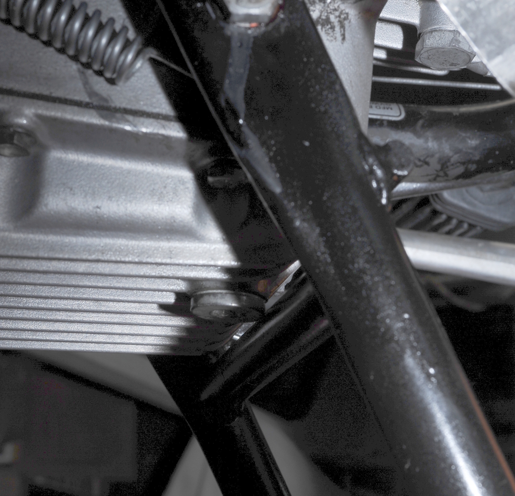
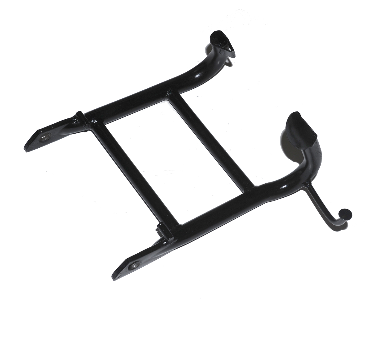
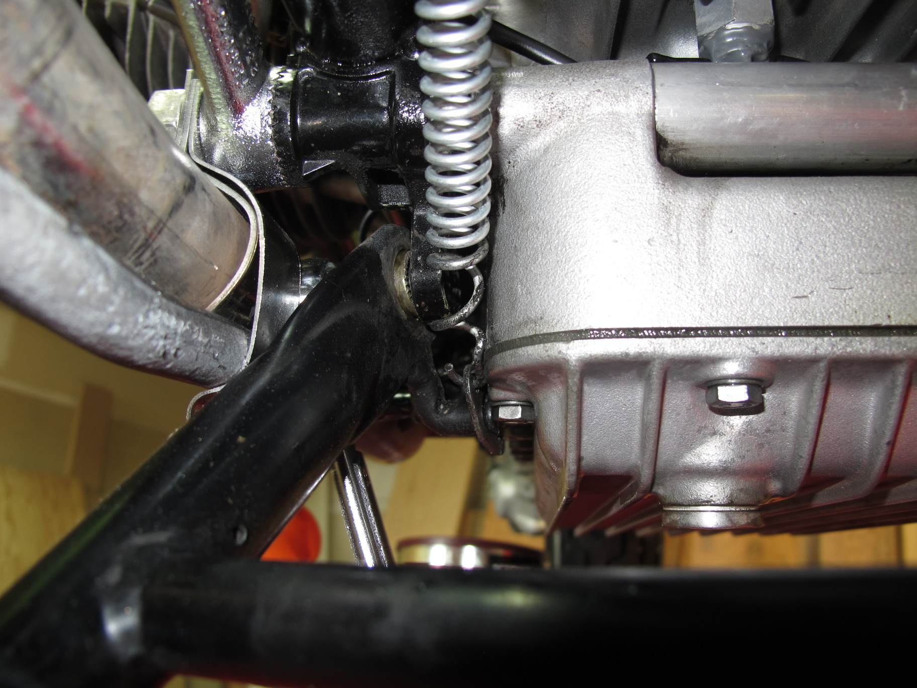
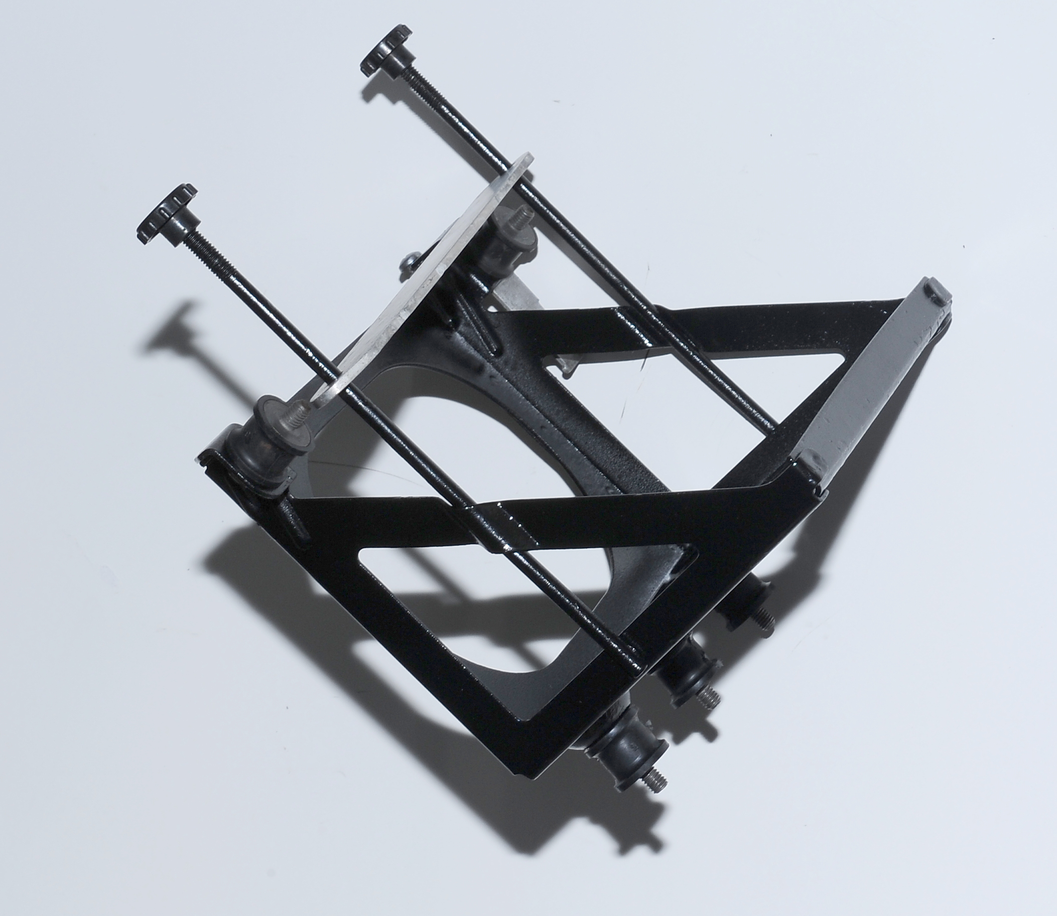
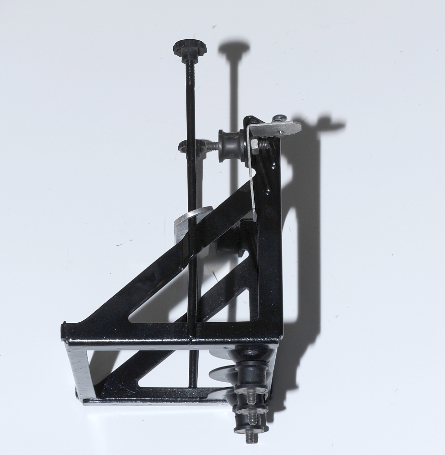
After installing the stand and springs I used a bottle jack to lift up the bike so that I could test the full range of motion on my rebuilt center stand from a 1976 R90/6. I’m glad I did this test because I discovered the stand won’t work on my bike despite checking and cross checking BMW part numbers.
The problem is the top cross bar. It clears the oil pan well enough, but not the drain plug. Not even close. Bummer.
With the factory stand option removed, I’m going to re-install the Reynold’s stand.
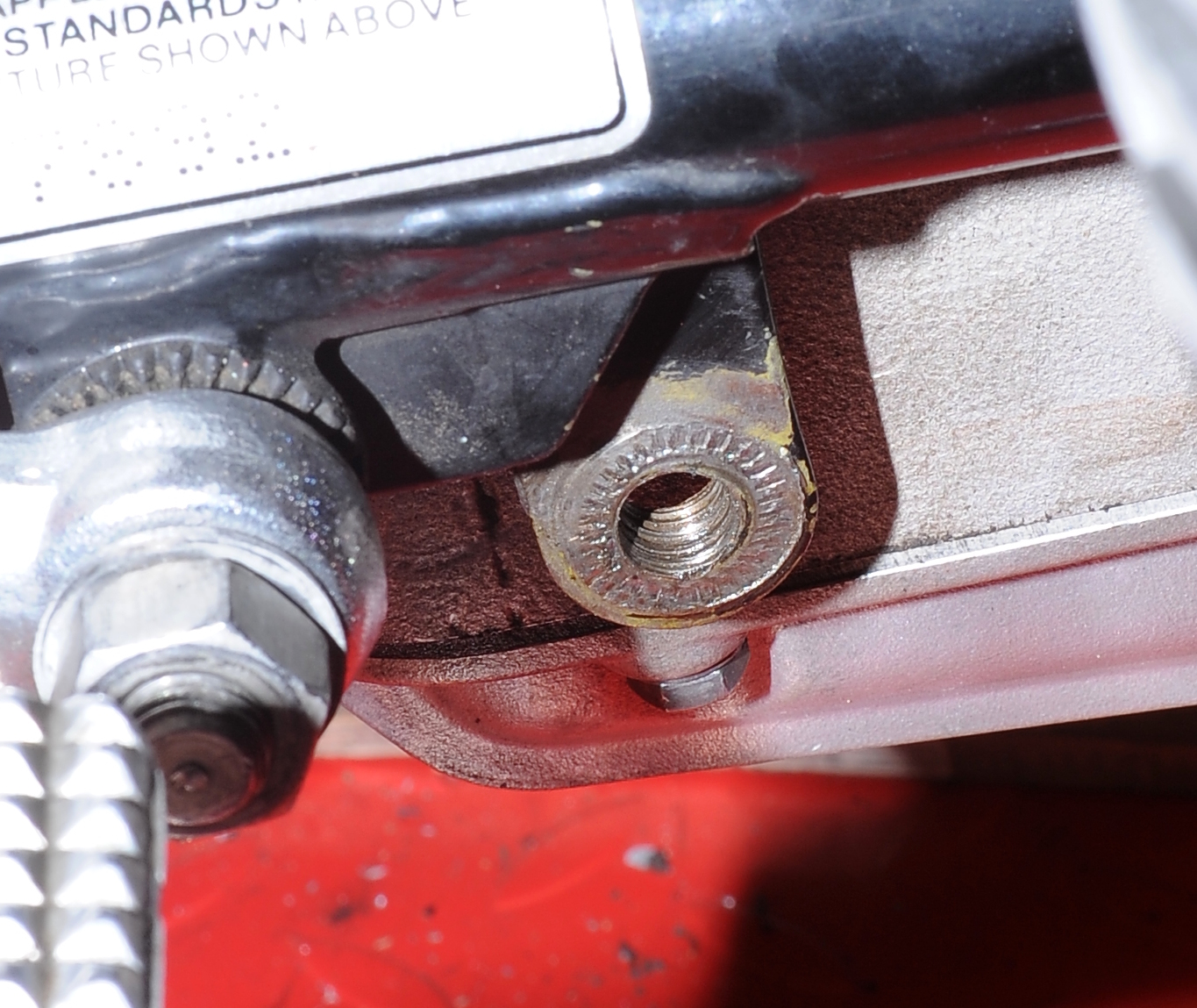
The first step in the center stand repair was to deal with the frame mounting points. While the threads were damaged, I was able to clean them up with a tap. Here’s the cleaned-up left-side threads.
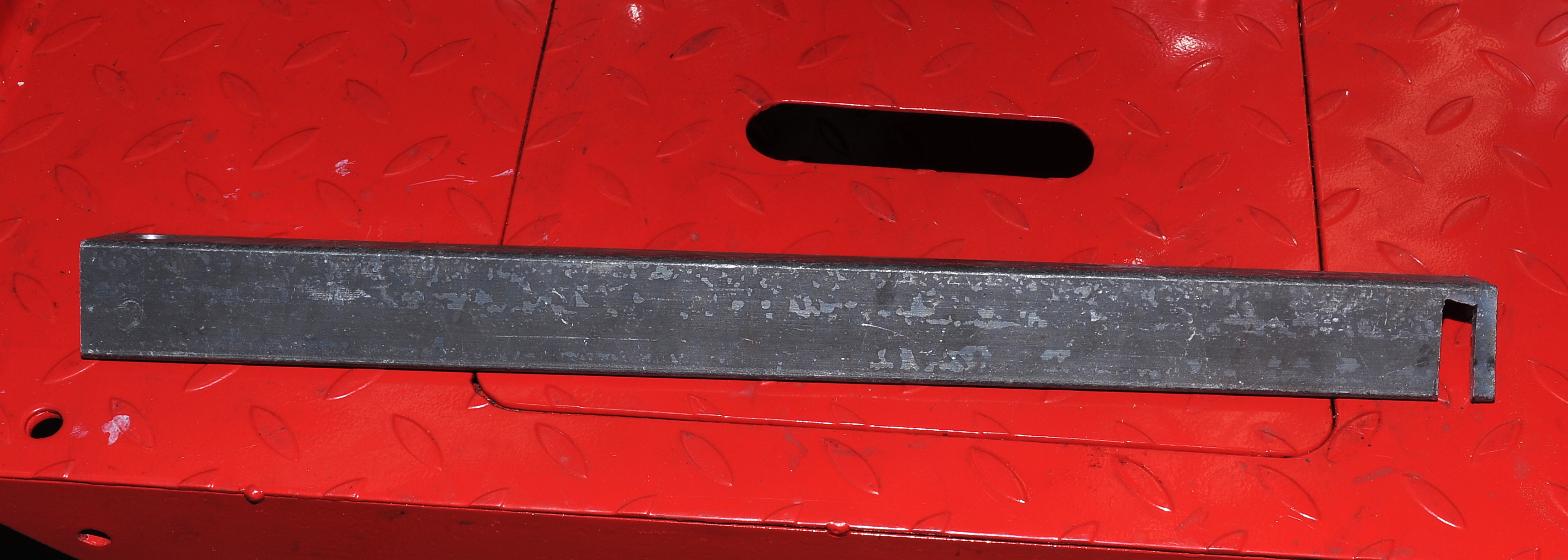
The left-side tab was slightly bent with the front edge being slightly closer to the engine case than the back. Though it doesn’t seem to interfere with the operation of the stand I was concerned about uneven pressure on the bushing so I made a tool out of a piece of scrap angle iron to straighten the tab. It worked well.
Here are the right-side threads. The first few threads aren’t as well defined as I’d like, but with proper length bolts, not the shorter ones that were in the bike, I think the repair will be strong enough.
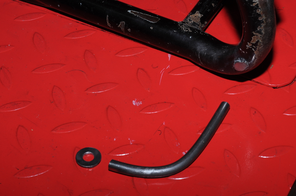
With the threads cleaned up, I could mount the stand and cut the 5/16″ rod to length. The washer will be welded onto the end to make it easier to catch the foot tab with a boot.
After the washer was welded on, the new peg was tack welded to the stand for a final fitting. I’ve angled the peg slightly forward primarily to leave more clearance between the ground and the peg when the stand is being used. This reduces the chances of a rock putting pressure on the peg when the stand is deployed on uneven ground.After the final tweaks, the rod was TIG welded to the stand, taking advantage of some of the original weld.
After two coats of primer and several top coats, the repaired stand is ready to be re-installed.
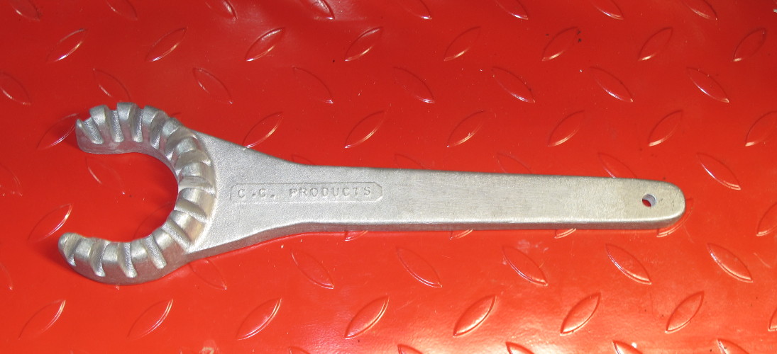
To properly repair the center stand I have to remove the exhaust headers. That requires a special wrench which just came in the mail. I bought this one on eBay. It’s not steel, but looks strong enough to do the job.
The tool is fine, but even with a large rubber mallet the nuts weren’t budging.
As the right-side nut was already pretty mangled from someone else’s attempt to remove the nut without a proper wrench, I decided to cut that one off rather than risk thread damage. Various sources suggest cutting or drilling to 4mm depth and then splitting the nut with a cold chisel. I didn’t cut quite that deep, though I now believe that is a safe depth. As a result I didn’t manage to split the nut, but in my attempts, I finally saw the nut move. It then came off easily using the wrench. The good news is that the threads look great!
Right side nut, previously damaged.
The left-side nut wasn’t visibly damaged like the right, but even with heat and a hammer I wasn’t able to get it loose. Not knowing what conditions the threads were in, I decided against using a breaker bar. So, using a hacksaw blade I again cut down about 3mm, and with a chisel, knocked the nut loose. I still didn’t manage to split the nut, though I probably stretched it a bit as I drove the chisel into the cut. Threads are in great shape here too. In hindsight, I probably could have saved this nut with a bit more leverage on the wrench.
Right side exhaust nut
I decided to purchase a used center stand from the same excellent eBay seller that sold me the rear wheel. When the stand arrived I was a bit concerned that it was damaged, not because the foot tab on the left side was broken off, that I could see from Alan’s pictures, I was concerned because it looked as though the the right foot was bent inwards. It turns out that’s normal. After a quick test fit I could see that the foot is bent inwards to avoid hitting the rear brake pedal. It had to be something like that, there just wasn’t any other evidence to suggest that the stand was damaged.
According to Alan’s description, the stand is “from a 1976 R90/6 with 10K miles showing”. I believe that to be correct as there’s only a modest amount of the usual wearing away of the tubing at the bends. There is a bit of surface rust and minor pitting, as you can see.
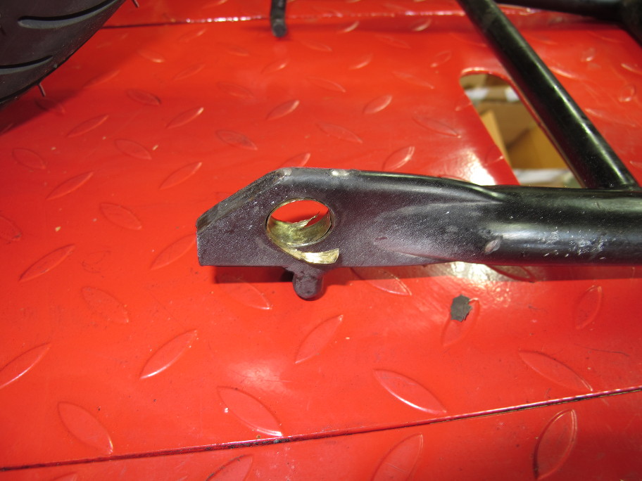
I picked up some 5/16″ rod at the local hardware store to replace the missing foot tab, which seems to break off of most of these stands; I couldn’t find a used stand with the original tab! As you can see, I’ve already put a bend in the rod. The next steps are to get the stand installed so that I can fit, and then weld on the new rod.
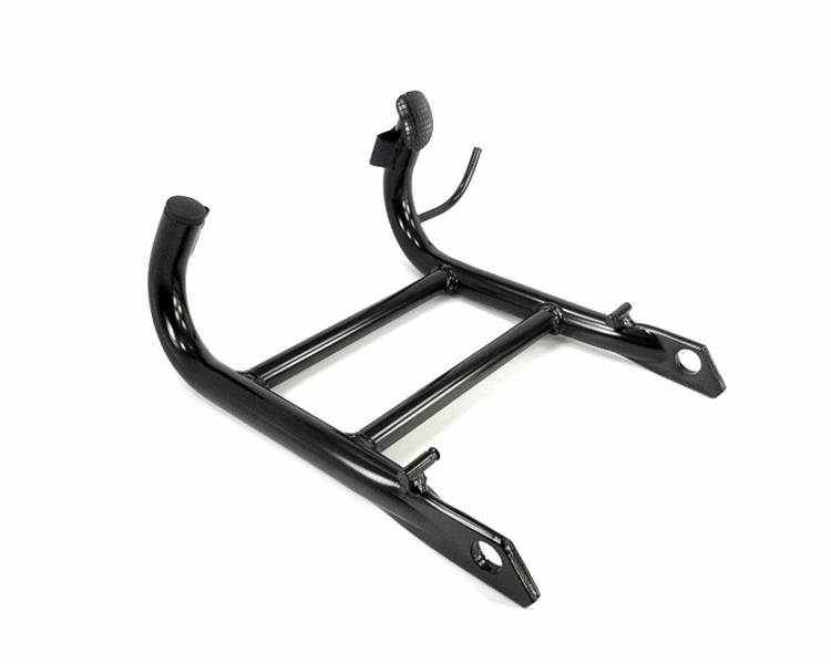
Here’s what a new center stand looks like.
After being able to compare the two stands side-by-side, I’m currently undecided on which one I want to put back on the bike. Here’s how the two center stands compare.
After a great first ride, I was moving the bike in the garage, putting it back up on it’s Reynolds Ride-Off after-market center stand, when it failed. Fortunately, a wall kept me from dropping the bike completely, though there is some minor damage to the fairing. I’m just glad it didn’t fail when I was putting the bike on the lift!
After recovering my wits and getting the bike on the lift to investigate the failure, I found that the center stand’s right pivot bolt was missing. It was found on the floor of the garage near where I first parked the bike after the trip. I also found two parts of a bushing (left side of next picture). I found the third chunk after taking this picture.
The bolt and bushing on the right side of the picture above were still in place, but not providing much support, as you can see from the picture below.
What’s a bit scary, if you look at the bolt on the right, is that there are only two threads that extend beyond the bushing. The bolt on the right side of the bike didn’t have a washer that I could find, so it had at most three threads engaged. That’s the bolt that must have loosened during the ride. All I can figure is that someone used shorter bolts rather than pull the exhaust headers, there’s not much clearance otherwise.
Here you can see the center stand pulled over towards the left side of the bike after the right side let go. I’m guessing that there’s some thread damage that I’ll have to deal with, though with so few threads engaged, there are probably still a fair number of good threads in the brackets.
Both the bolts and the stand have this copper-colored thin steel shim material. I suspect this is a repair. As you can see, what the center is lacking, is grease.So, when was the last time you checked your center stand? It was on my list of things to service, but not high enough on the list, obviously.
I now need to decide if I want to replace the after-market stand with a factory stand, or try and repair this one. This stand is easier to get the bike up on, but it doesn’t allow you to service the wheels. Perhaps I’ll try and find some bushings for a temporary repair while I search for a factory stand.
There was one bit of good news. While taking pictures of the center-stand I caught a glimpse of the repaired neutral switch. No oil leaks! At least not yet.
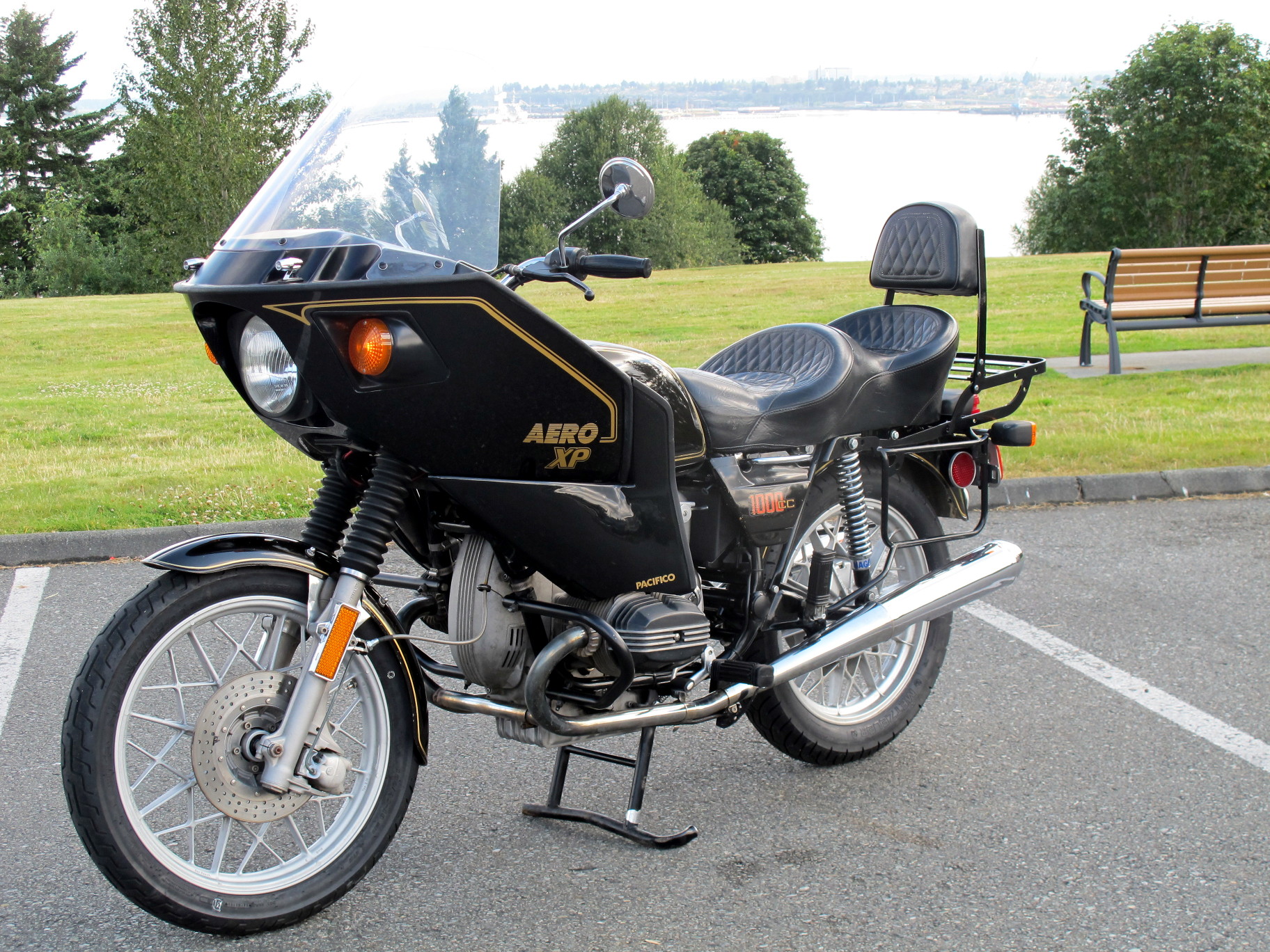
After a few short rides to make sure everything was working reasonable well, I took the bike for a longer ride that included a mix of back country roads and 60-70 MPH freeway driving. The bike did well.
First Test Ride — Left saddlebags at home
Here’s a summary of what I discovered.
The gearbox takes some getting used to.
The bike handles well, and is quite comfortable at freeway speeds
There might be a small oil leak on the push rod tubes on the left side. Not too much of a surprise.
The front bearings ran nice and cool.
The rear bearings were slightly warm to the touch after many miles of 70 MPH, but I had also just used the rear brake.
The high-beam indicator doesn’t work
The neutral switch is working, but the light shows symptoms of a bad diode. The light comes on when you pull in the clutch which is not helpful when you’re trying to find neutral!
The turn signal beeper works, but only when the bike is in gear, the clutch is out, and the RPM’s are up (further evidence of a weak charging system).
The odometer is not to be believed!
When I bought the bike, the odometer read 74,833. After what I was sure were short test rides, the odometer read 75,013. Near the start of today’s ride I reset the trip meter when I bought gas. At the end of the ride, the trip meter, which I checked against mile markers, read 69 miles. The odometer is now at 76,252, which if correct, suggests that I rode more than 1200 miles in a couple of hours.
Mounted and balanced new rear tire: Metzler Lasertec 4.00v18
Balanced with 40g
Cleaned and greased rear wheel bearings, replaced both seals
Greased final drive splines: moly
Re-installed mufflers (copper anti-seize on headers)
Re-installed battery, seat, side covers, windshield and right mirror.
Re-installed carburetors
Installed wheel and axle:
Axle nut torqued to 26 ft-lbs
Axle clamp torqued to 11 ft-lbs
Tire Pressure:
Front: 34 psi
Rear: 37 psi
It’s taken two and a half months, but the bike is finally ready for a test run.
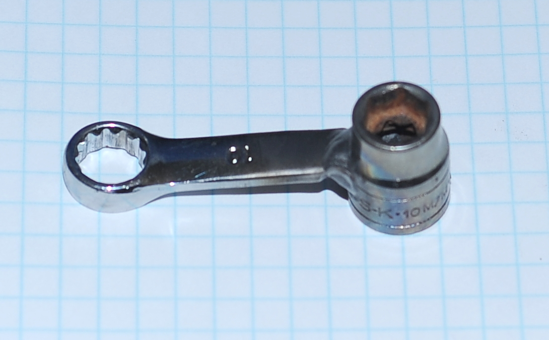
Torquing the drive shaft bolts requires a 10mm offset socket. You can buy these from Snap-On, or other places that sell airhead parts. Even though I have no welding skills, I managed to weld up a tool using an old socket and wrench. The only mistake I made was not making sure that the 3/8 in drive (which you can’t see) was square to the wrench. This isn’t a problem with a ratchet-style torque wrench, but with a beam-style wrench, I can’t get the adapter at either 0 or 90 degrees to the wrench.
Today’s task was to finish the battery tray restoration and install it back in the bike. The restoration involved removing the rust, repainting, and restoring the rubber. The tray was painted with one coat of Rustoleum, and then three coats of black lacquer with a bit of light sanding between coats. If this doesn’t hold, I’ll pull it out and have it powder coated.
The aluminum hold-down bracket looks hand made. It certainly isn’t original.
You can still buy the rubber mounts, they cost about $13 each. I chose to restore them instead by soaking them overnight in a mixture of rubbing alcohol and wintergreen oil. They swelled up a bit, but after setting for a while they returned to their normal shape. The rubber feels normal now, not so hard, and the battery tray now moves a bit allowing it to soak up shocks and vibration.
There are five rubber mounts. The rubber mount holding the buzzer and relay bracket shown in the picture below is different from the other four. It has one long stud which was installed on the bracket side when I pulled the battery tray from the bike. As you can see, even with the bracket mounted, there’s quite a bit of thread left over. In the fiche at MaxBMW, they list the mount’s part number as 61211233028 up to 09/77 and part 61211243530 post 09/77. The picture of the earlier part looks like the four mounts with the short studs, and the later the mount with the one longer stud. As this bike was built right about that time period, perhaps they were just grabbing whatever was left in the bin. Or, perhaps they were using two different parts until 9/77 and decided to simplify their BOM.
I’ll be keeping an eye on the buzzer bracket. It wasn’t corroded, but if I start to see any corrosion, I’ll probably zinc-plate it.
Installation Note: If the swing arm is installed it’s easier to install the three lower rubber mounts in the frame before installing the battery tray. This method makes it easy to spin the rubber mounts from the top to get the nut started. There’s just enough room between the swing arm and the frame to get a nut positioned with your fingers, but not to turn it. Once started, you can use an open-end wrench to tighten the nuts.
The final drive… has arrived! It’s time to start putting the bike back together.
Today’s Summary:
Installed replacement oil pan and gasket, pan bolts torqued to 72 in-lbs
Added engine oil, Castrol GTX 20-50 (SJ)
Reinstalled swing arm, shocks, final drive
Shocks bolts torqued to 25 ft-lbs.
Final drive-to-swing arm bolts torqued to 22 ft-lbs
Swing arm pins torqued to 180 in-lbs and then to 100 in-lbs
Swing arm lock nuts torqued to 75 ft-lbs
Greased swing arm bearings: NLGI 2
Added final drive oil: Sta-Lube 80W-90
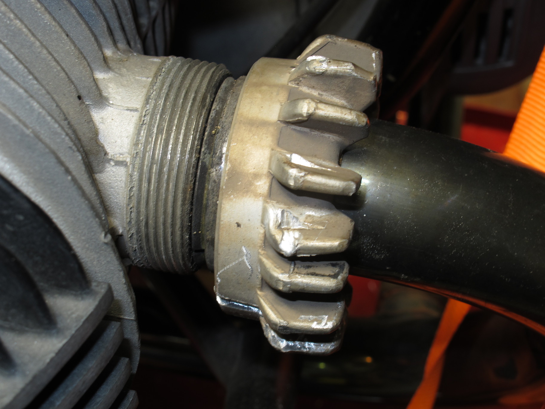
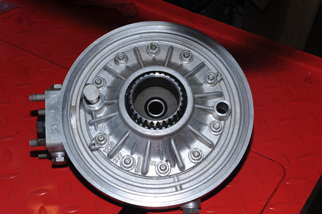
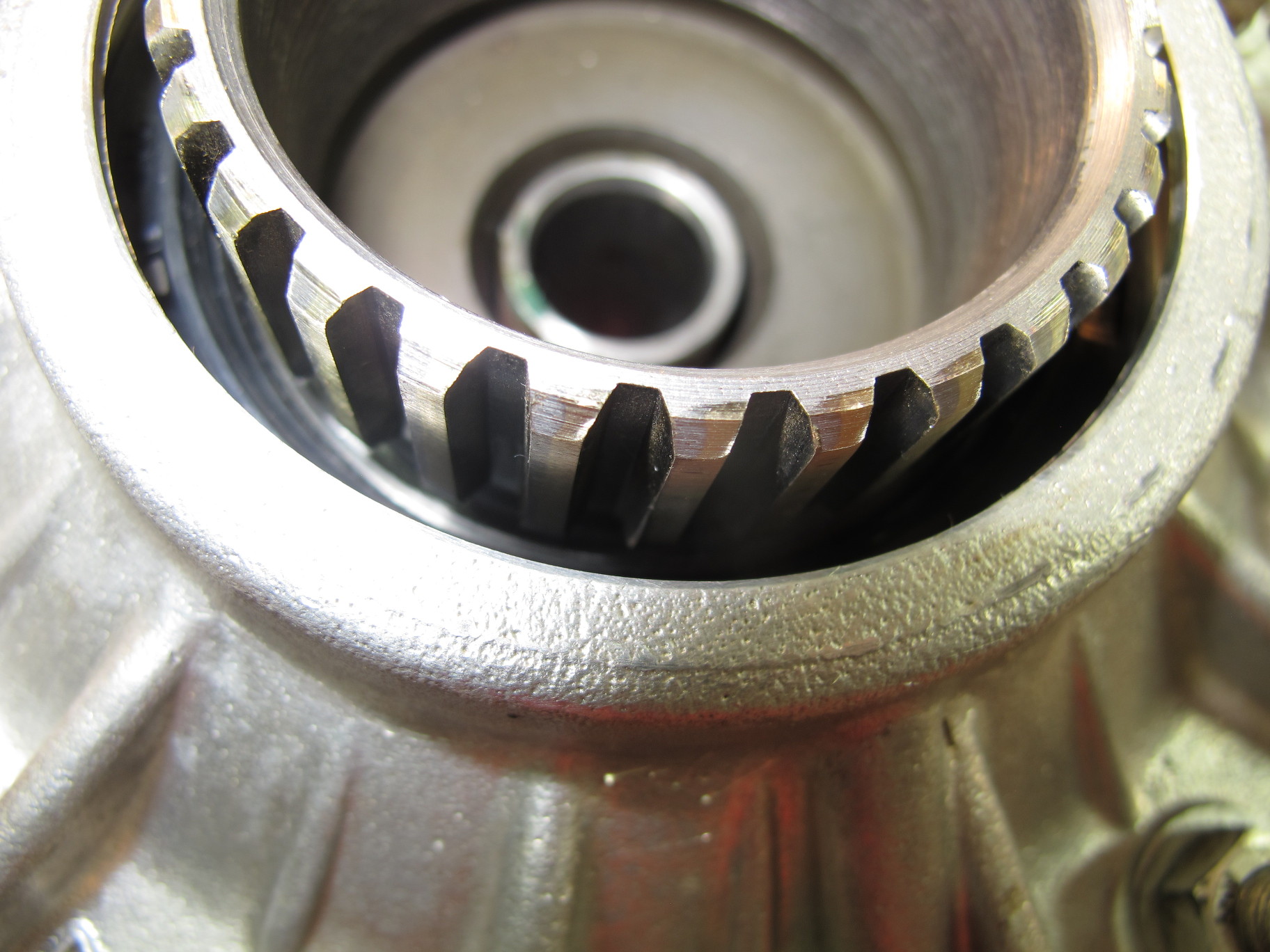
I had Hansen’s Motorcyle in Medford, Oregon rebuild the final drive. In addition to re-manufacturing the splines, they also replaced the main bearing and seals. I’m quite pleased with the results. I also really appreciate Hansen’s attention to detail. They included the paper swing arm gasket, and it looks like they may have included new crush seals for the filler bolts. They also returned the parts they removed.
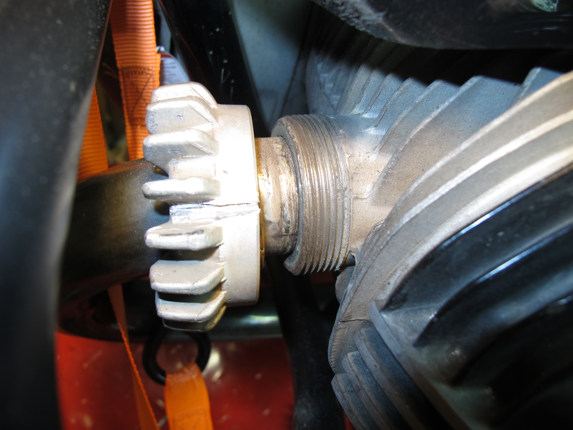
Here’s a closeup of the new splines.
While the swing arm is back in the bike, I still have to build a tool to torque the drive shaft bolts. I have new bolts, which are shorter than the bolts I removed as the new bolts don’t use lock washers.
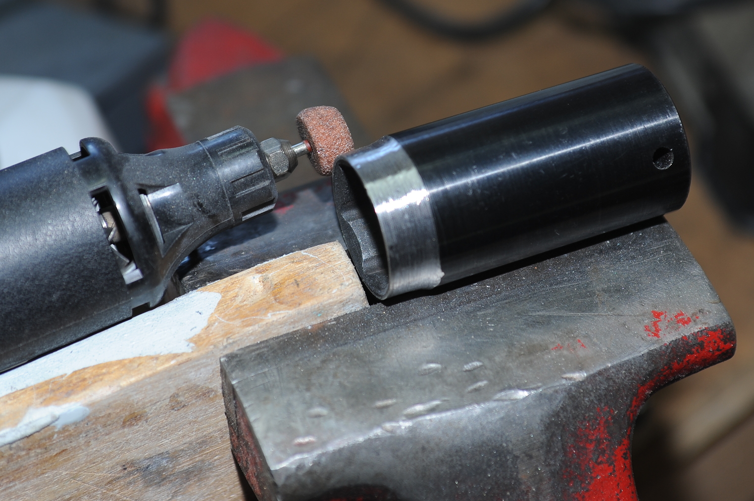
To remove and install the swingarm nuts I had to modify a 27mm socket. The proper way to modify the socket is with a metal lathe. I don’t have one of those, so I used a Dremel tool with a grinding bit as shown here.
To make the grind, I would spin the socket with the palm of my right hand. I held the Dremel tool with my left hand, applying pressure when the socket was spinning, and removing pressure as I ran out of palm. It wasn’t fast, but accuracy was surprisingly good. The wood block is there to provide a stop for the socket to rub against while turning, preventing left-right movement. If you try this, don’t forget to wear eye protection.
I used the swing-arm adjusters to center the swing arm with some pressure from the pins (to preload the bearings. Once centered I torqued the adjuster pins to 180 in-lbs, backed them off slightly and torqued to 100 in-lbs. The adjuster nuts were torqued to 75 ft-lbs.
The Clymer’s manual indicates the the drive shaft splines at the final drive input are supposed to be greased. This confused me for a bit as the drive shaft spins in gear oil. I finally decided that it must be for assembly purposes, so I put a little bit of general purpose axle grease on the splines expecting that it will wash away in the gear oil.
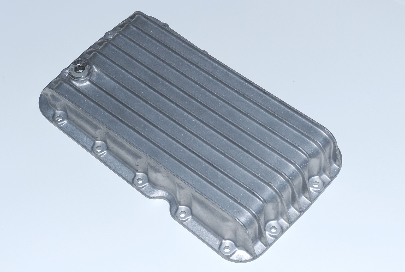
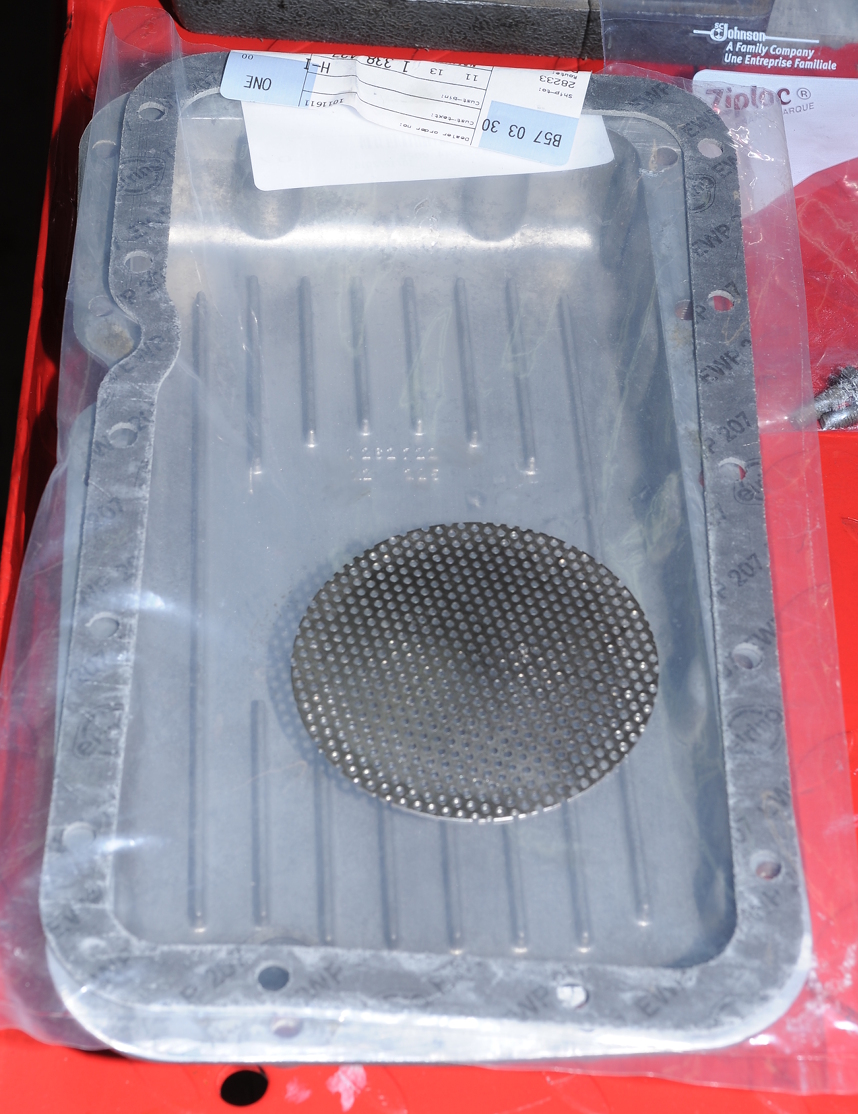
The used oil pan I bought earlier has been cleaned up and is now ready to install.
Media blasting removed most of the corrosion that was on the pan. It looks pretty good now, not that you’ll ever see it on the bottom of the engine.
I removed most of the old gasket with a razor blade, and then went around, lightly, with a fine sharpening stone to remove any remaining gasket material. The mating surface was in good condition, free from any scrapes and gouges.
With the new pan ready to go, it’s time to pull the old pan.
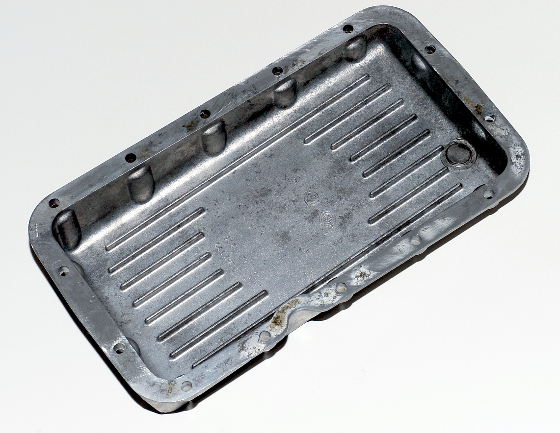
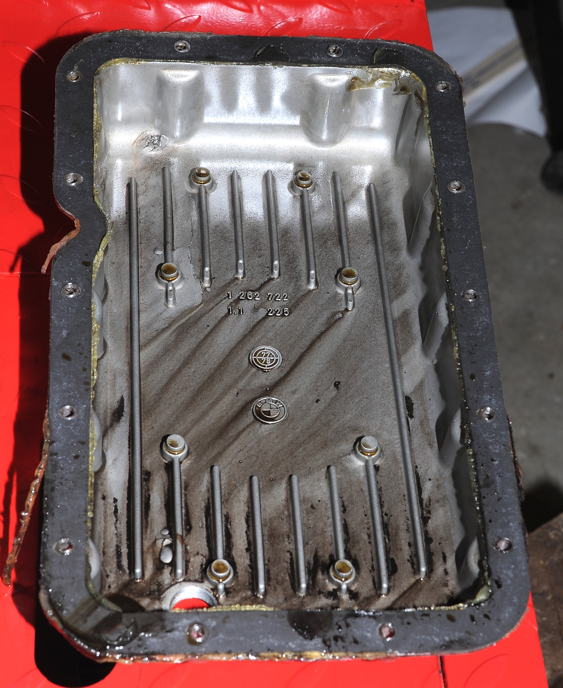
Well, there’s some sludge, but without knowing how long it’s been since the pan was removed and cleaned I can’t really draw any conclusions other than it’s not full of sludge. The oil is pretty dark. If you look closely in the upper, left quadrant of the pan you can see damage along the front edge and a large crack between a couple of the fins (click on the picture for more detail).
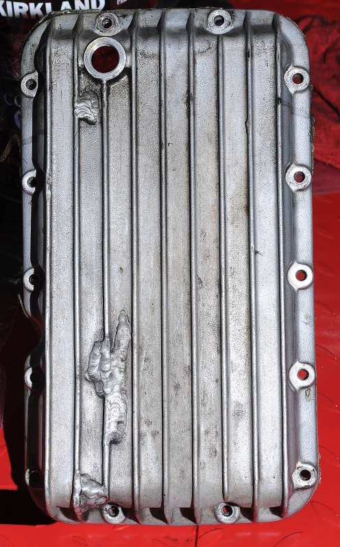
Here’s the bottom of the pan. The repairs aren’t pretty, but they do look strong.
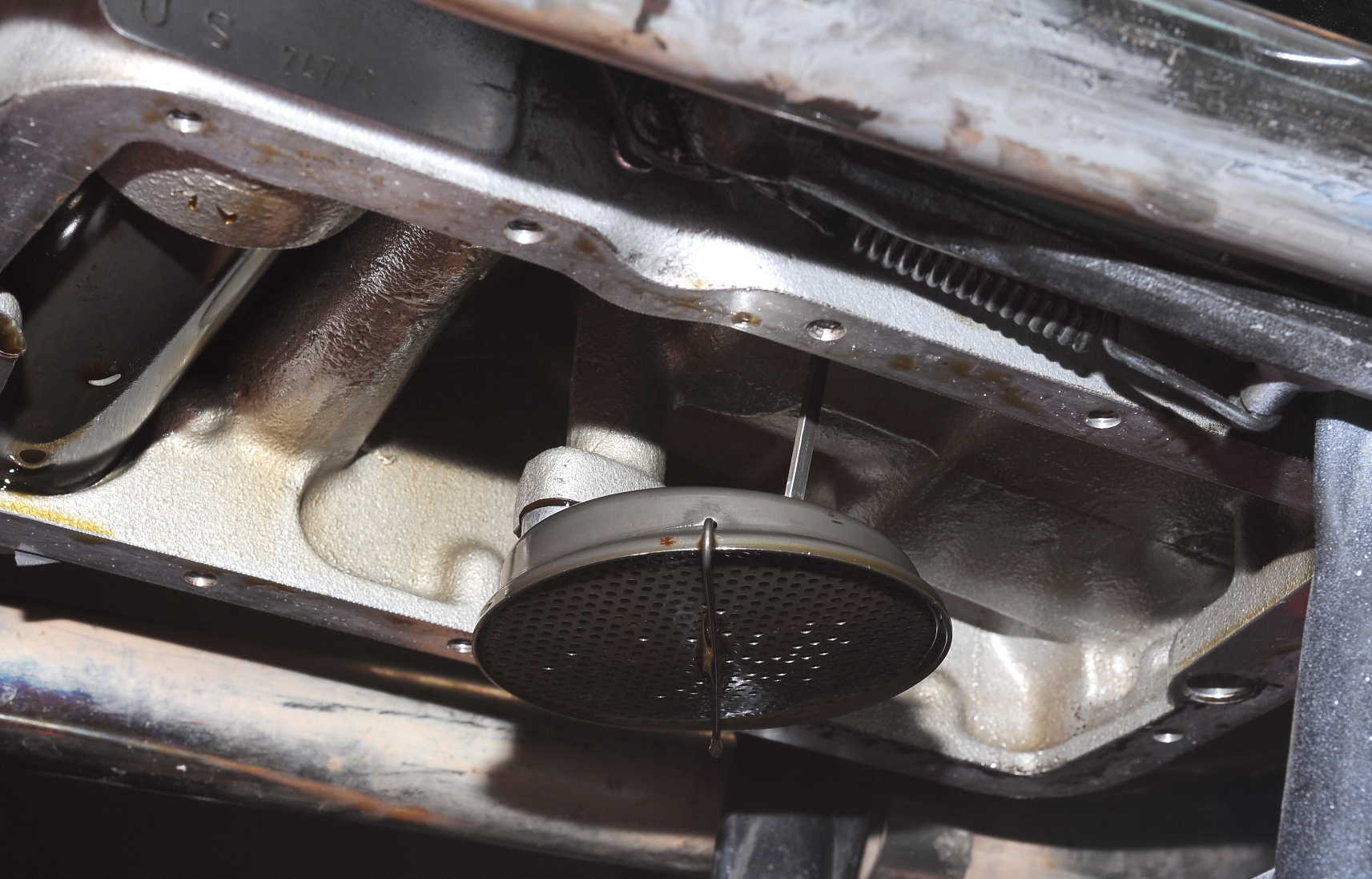
Other than being coated in dark oil, the screen filter is clean.
I pulled the screen, cleaned off the oil, and gave it a good inspection. All is good. Here are the parts all ready to be installed.
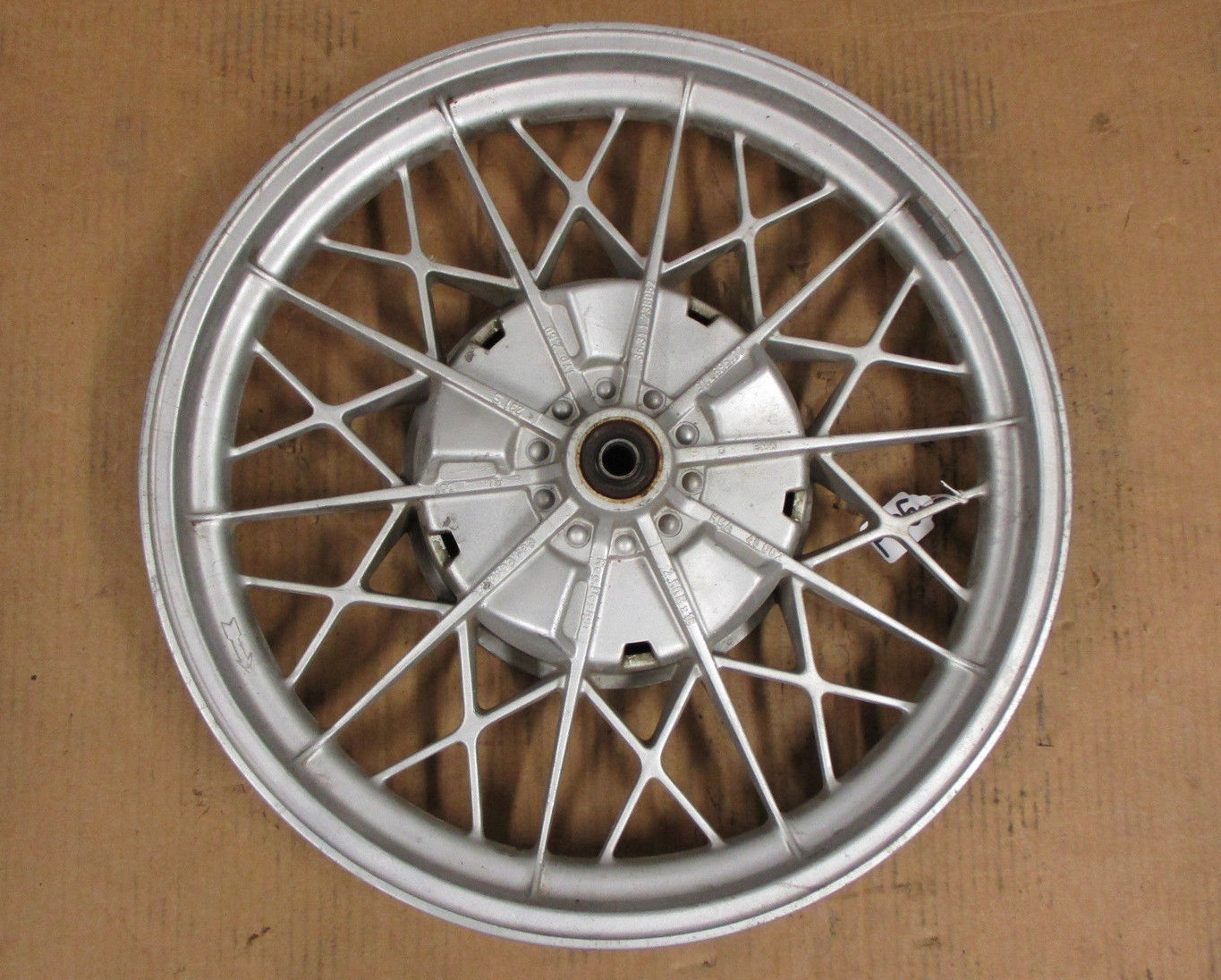
After looking at lots of tired and bent wheels for sale, I finally found this one on eBay. According to the seller it has a date stamp of 12/78, so it probably came from a ’79 bike. It looks like it will clean up nicely.
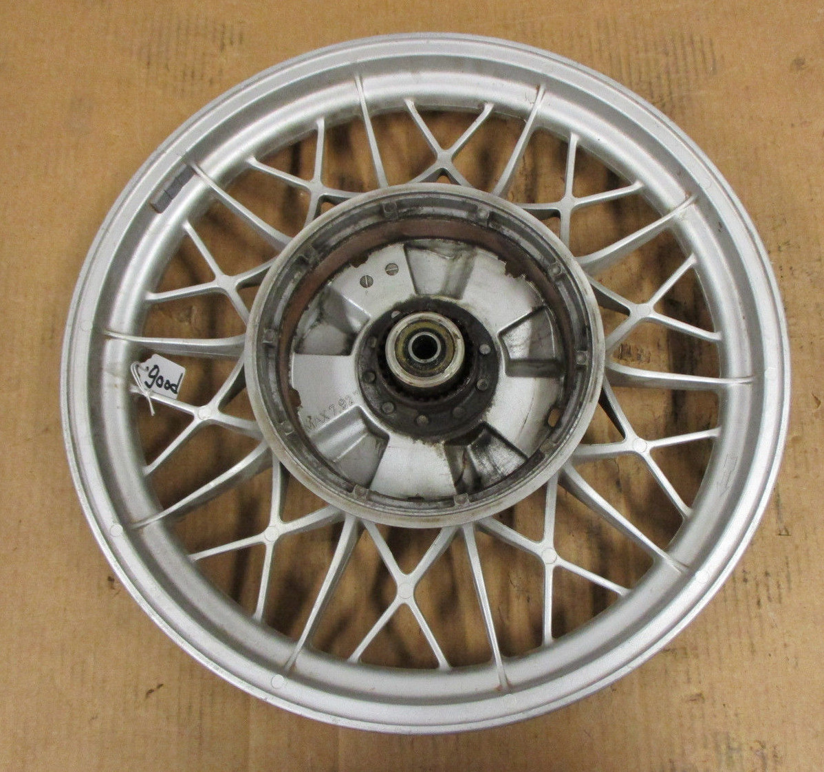
There are some interesting differences between this wheel and the one it’s replacing. In the earlier wheel, there are raised vents with plastic grills to scoop in air. In this wheel, the raised portions of the hub are still there, but the vents are not cut out.
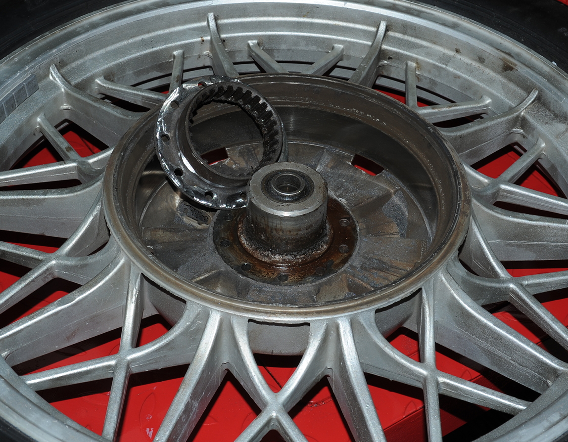
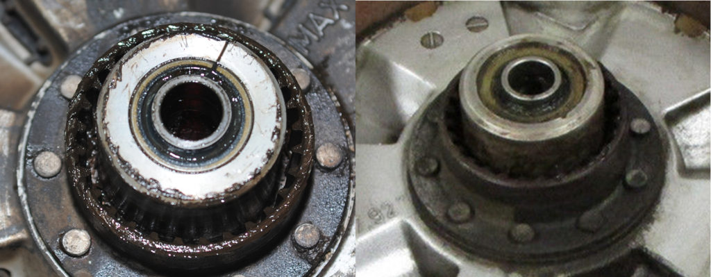
On the inside of the hub, they’ve added the 10 bars that you can see running between the brake lining and the edge of the hub. Perhaps these are meant to move air around? They’re also lined up with the radial spokes, so more likely they’re there to stiffen the hub around the brake lining.Those bars aren’t present in the ’77 wheel. If you look closely, you can see one of the black plastic vents below the left edge spline cup. Click on the picture for full resolution.The ’77 wheel on the left is aluminum alloy and has a smaller, 35mm seal on the right side, and a 36mm seal on the left. The right bearing is pushed in from the left side. The ’78 wheel is also aluminum, except for the hub center which contains a steel sleeve. The bearings are pressed in from both sides on this wheel and both seals are 40mm. Both of these wheels use the same bearings, which is good, because I’d already ordered a couple. These bearings are also used for the swing arm and front wheel.
As soon as the new wheel arrives I’ll get to start over on splines and bearings. Yeah!
 The problem is the top cross bar. It clears the oil pan well enough, but not the drain plug. Not even close. Bummer.
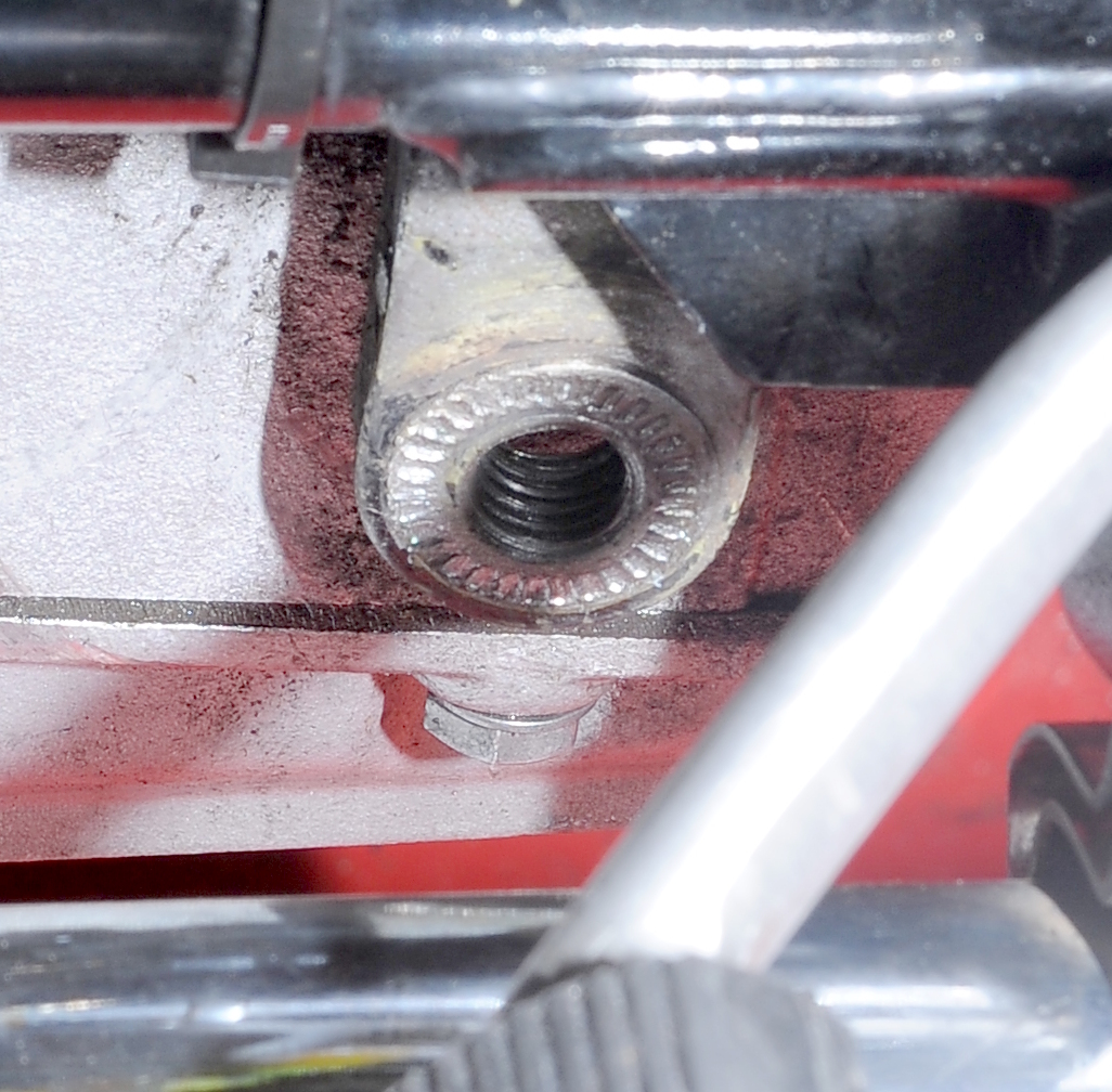


 As soon as the new wheel arrives I’ll get to start over on splines and bearings. Yeah!