While there’s a lot of very useful information about airhead clutches on the web, I found that there wasn’t any one site that explained the operation of the clutch well. So I’ll attempt to do that here.
Unlike most Japaneses bikes of the time which used multi-plate wet clutches, the airhead clutch is a dry clutch similar to what you’d find in a car with a manual transmission. They work well, but like brakes, they generate a lot of dust as they wear.
In this diagram we have:
- Diaphragm spring which presses against the flywheel.
- Pressure plate.
- Friction disk, or clutch plate.
- Compression ring.
- Six bolts that compress everything against the flywheel.

Here are the actual parts. The pressure plate (2) is the one in the upper, left. The compression ring (4), with it’s built-in spacers is on the lower, left. Doesn’t quite look like the diagram, does it? The spacers provide room for the friction disk which is sandwiched between the compression ring and the pressure plate. The gaps in the spacers probably also help with cooling and allow the clutch dust to escape
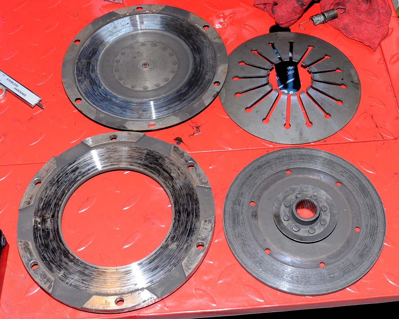
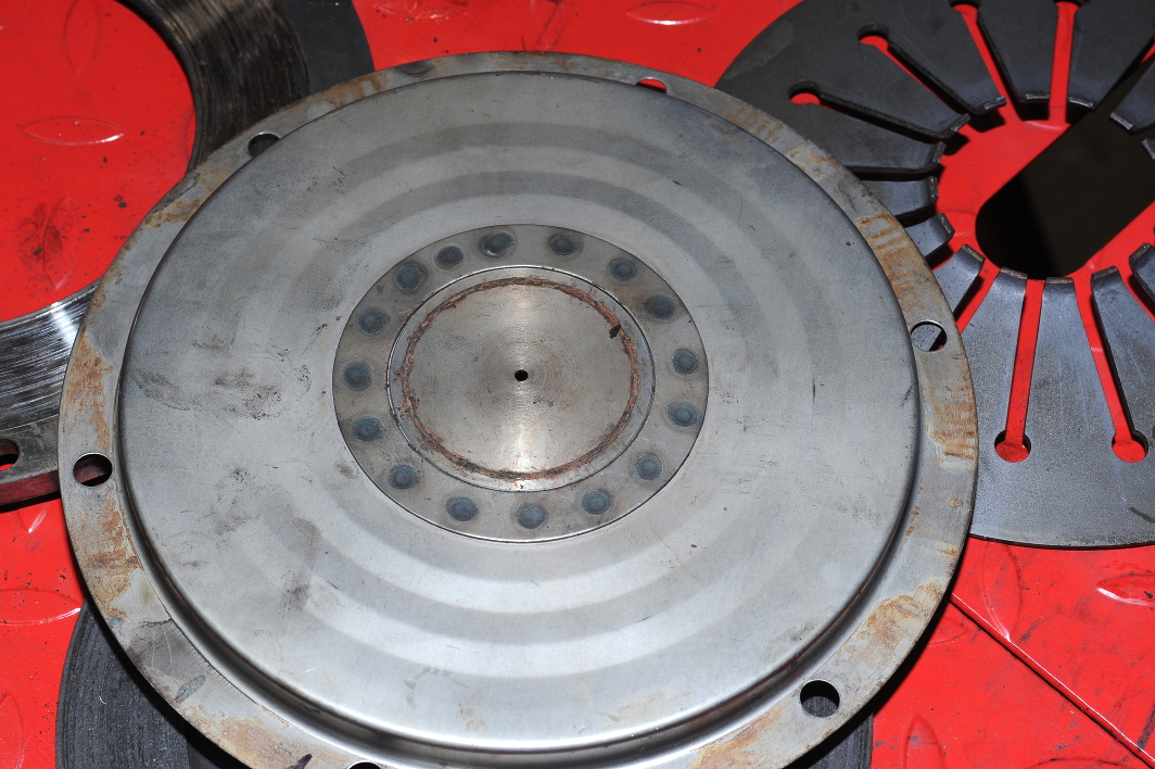
What’s usually not explained very well is that the friction plate wears on both sides as it slips between the pressure plate and the compression ring. All three parts wear as you can see in the picture above. The friction disk does not wear against the flywheel, as it does in many automobiles.
When assembled, the outer edge of the spring presses against the flywheel while the fingers apply pressure to the back of the pressure plate, which in turn pushes the friction plate against the compression ring. With the friction plate tightly sandwiched between the pressure plate and the compression ring, it can’t slip allowing power to be transferred from the engine to the transmission through the splines on the friction plate.
Taking a closer look at the friction side of the pressure plate, you can see the conical indentation in the center. When you engage the clutch (pull in on the clutch lever), the clutch pushrod extends, pressing against that indentation, further compressing the clutch spring on the opposite side. This moves the pressure plate away from the friction disk, reducing the pressure being applied to it. With less pressure on that side, and assuming the splines have been properly greased, the friction disk moves away from the compression ring. No longer tightly sandwiched, the friction disk is new free to spin at a different rate relative to the engine. The indentation is also where the pointy end of your clutch alignment tool fits when you’re installing a clutch.
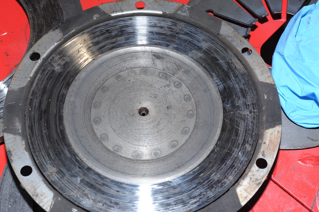
It’s worth noting that the thin outer edge of the pressure plate assembly (the portion with the six bolt holes in the picture above) is actually a metal pan which can’t move (e.g. slide on the bolts) as it’s tightly sandwiched between the flywheel and the compression ring. Instead, the pan distorts when the clutch lever is engaged, allowing the friction part of the plate assembly to move away from the friction disk.
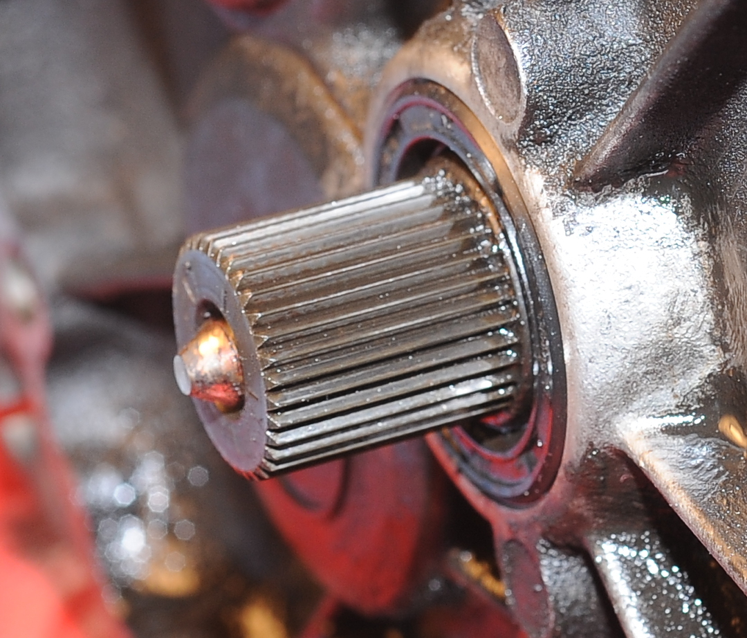
Here’s the clutch pushrod poking out through the center of the splined transmission input shaft. You can see it has the same conical shape. It extends out further when you pull in on the clutch lever. The rod passes all of the way through the transmission to the thrust bearing and clutch arm on the rear of the transmission.
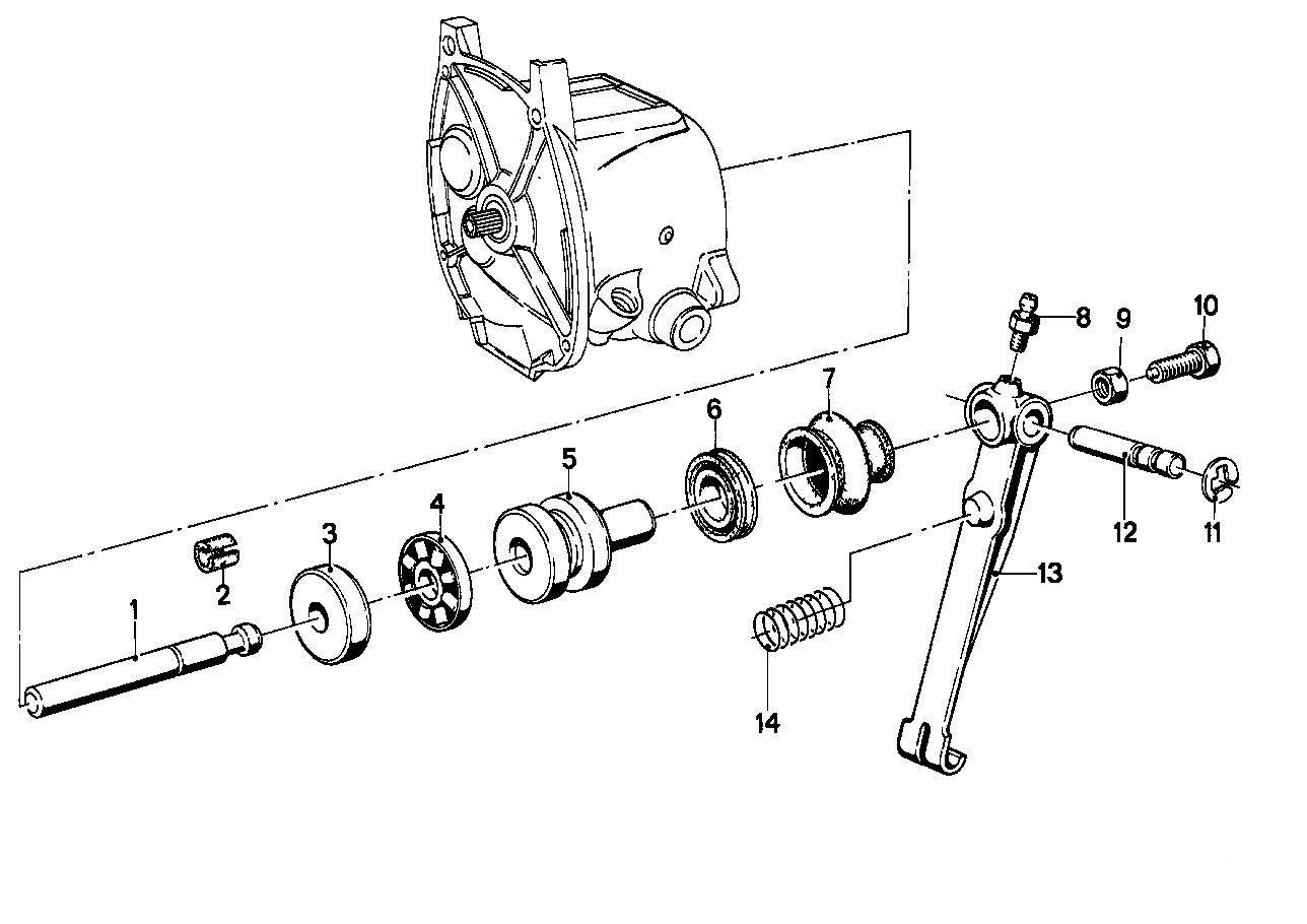
The pushrod is (1) in the following diagram. When you pull in on the clutch lever which pulls on arm (13), piston (5) pushes against the thrust bearing (4) and washer (3) which pushes the rod into the pressure plate. The thrust bearing allows the rod to spin so that the tip of the rod doesn’t wear against the pressure plate.
The bolts (5 in the first diagram) don’t pass through the diaphragm spring, so there’s nothing except pressure to keep the spring from spinning between the flywheel and the pressure plate. In theory, the spring shouldn’t ever rotate relative the the flywheel and pressure plate. However, as you can see in this next picture, there’s a wear ring. I suspect that inertia might cause the springs rotational velocity to lag the flywheel and pressure plate under hard acceleration. In other words, if you punch it in first gear, or you rev the engine while in neutral, the spring could shift relative to the flywheel (and pressure plate). That’s not a bad thing. In fact, it’s probably better than digging a fixed set of holes with the spring fingers, which is what would happen if the spring never shifted.
Here’s a closeup where you can just see that the spring did spend more time at some locations than others (darker spots at the bottom)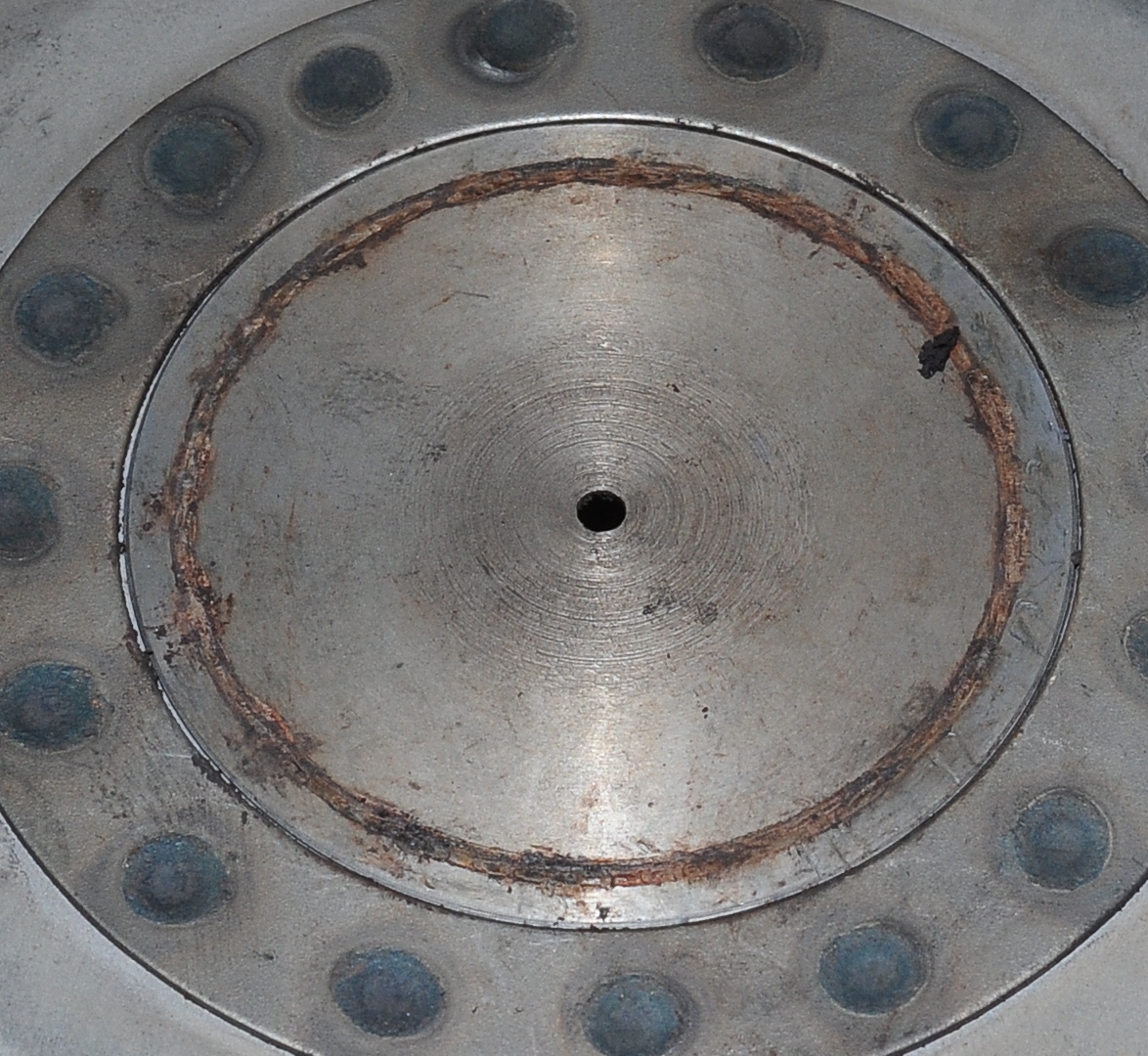
The wear ring was caused by these spring fingers, which are also slightly worn. As the spring is normally compressed, the wear is on the edge of the finger away from the center. In this picture you can see some wear on the finger in the upper, right (with numbers stamped on it). Other fingers, like the one extending from the upper, left corner of the picture, have nice square edges and don’t look worn at all.
So, that’s it. Not very complicated, but perhaps a little easier to understand when you can see pictures of the real parts along with the less detailed diagrams. I hope you found this helpful.