Mileage: 75,455
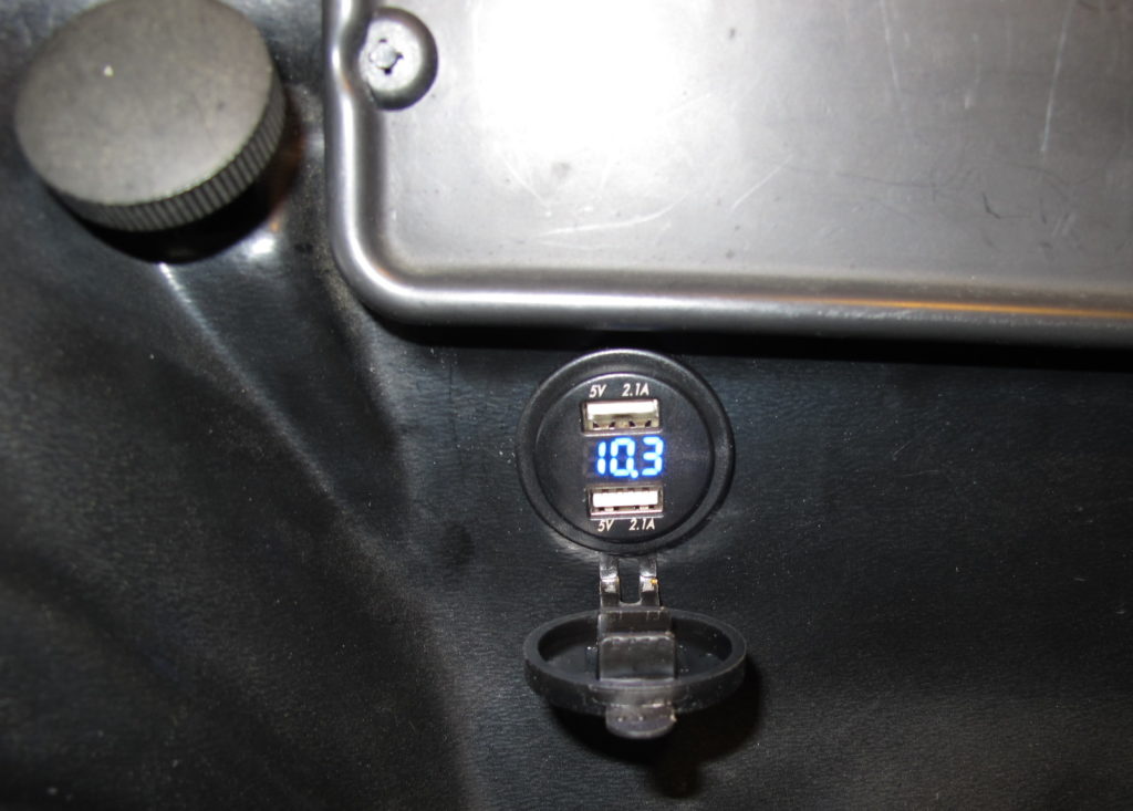
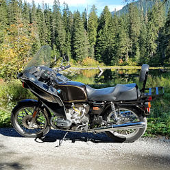
Today’s task was to add USB ports to the bike for powering a phone, GPS, or charge something while underway.
I found this little unit on eBay for $14.

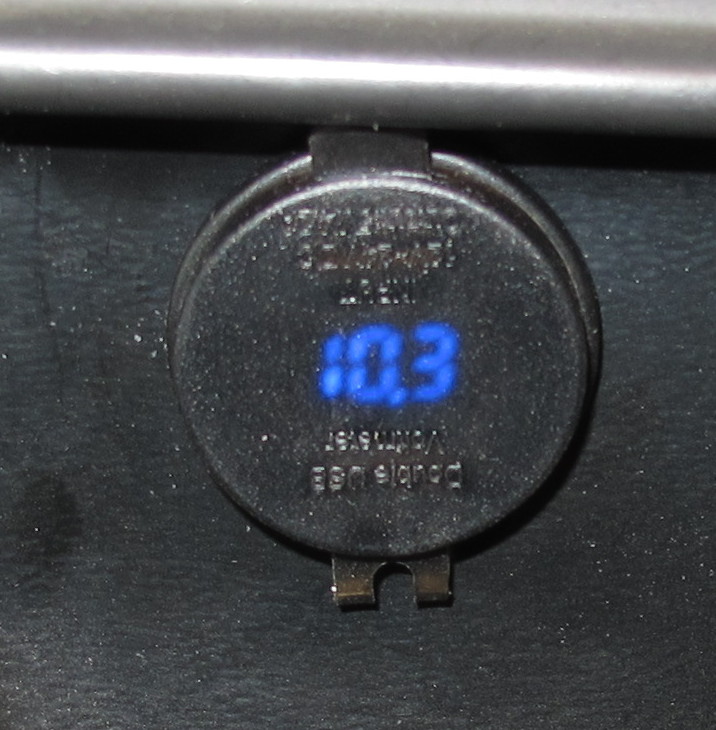
The weather cover is semi-transparent, so you can still read the voltage with the cover closed, though I suspect it won’t be easy to see in bright sunlight. The cover is currently oriented so that gravity will help keep it open. The cover isn’t keyed, so it can be oriented any direction. We’ll try this for a while.
 I was hoping, given there was a place for a radio, that there would be unused wiring that I could use to power this device. No such luck. I had to add a ground wire and pull power off of the switch. For the later I built a short splitter cable with spade lugs on the cable ends.
While the fairing wiring was in pretty good shape, it was a bit unusual. For example, there’s a plastic block with a diode hooked into the wiring harness. After a bit of poking around, I’ve decided that the diode is there to combine the accessory and run positions of the switch to power the running lights. I was hoping to be able to use the USB ports without turning on the headlight, but that would have meant connecting to the cathode side of the diode which is going to be at least 0.7v lower than the battery. As currently installed the meter and USB ports will only work when the key is in the run position.
As you can see from the reading, the voltage looks a little low. There are three reasons for this. First, the engine isn’t running and all of the lights are on, so the battery is being pulled down a bit. Second, when compared to my Fluke voltmeter, this meter seems to read about 0.1V low. The largest error comes from the fact that the grounds inside the fairing are not at the same potential as the engine. I’m not yet sure why that is. Either there’s another diode somewhere, or there are some ground connections that need attention. I suspect the later as the ground potential increases when the headlight is turned on. To troubleshoot this problem I’m going to have to pull the fairing so that I can get to the tupperware junction box.
Note 1: To pull the radio cover you need to pull the slender center pins to allow the larger split pins to collapse.
Note 2: I found a spare indicator bulb for the two red turn signal indicators in a bag tie-wrapped to the wiring harness. The right turn signal indicator doesn’t work, so I pulled the bulb. Unfortunately, the bulb is fine, so there’s another wiring problem that needs to be fixed at some point.


