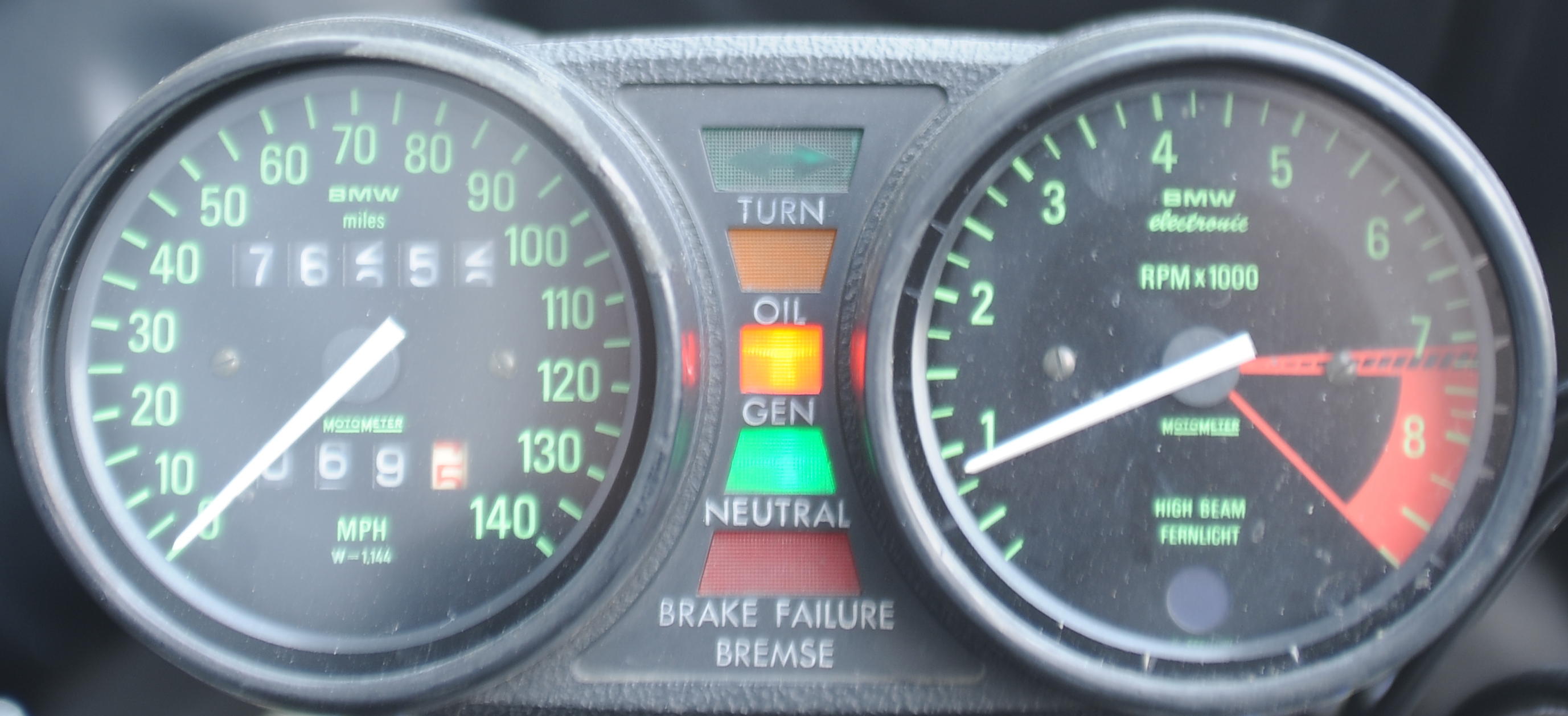
The instruments had several problems. As noted earlier, the odometer ran fast, even though the trip meter worked correctly. If you believed the odometer, I could get more than 1000 miles on a single tank of gas. The second problem was that the turn signal indicator didn’t work. The third problem was that the instruments no longer seemed to be sealed against moisture. They’re also in need of a good cleaning.
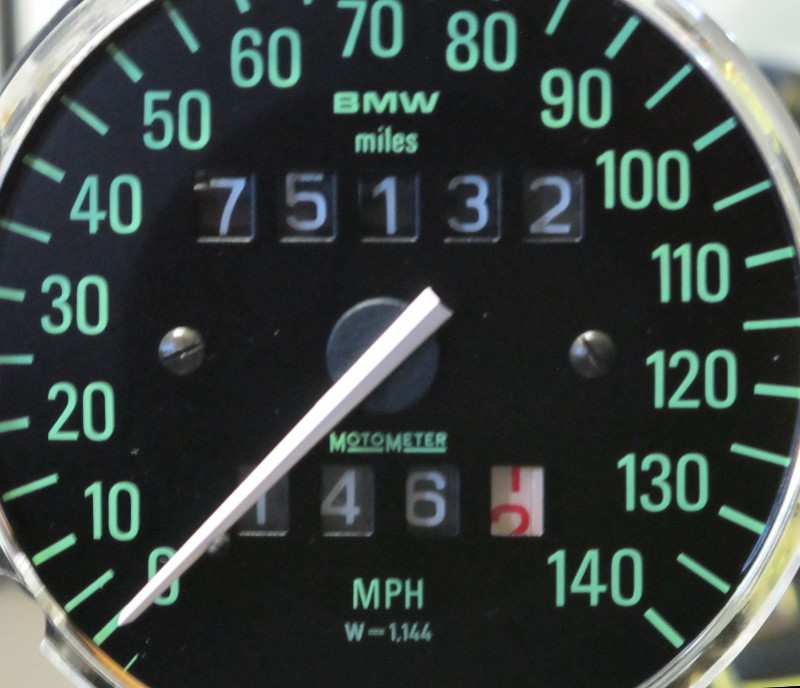
Here’s the before picture showing more than 76k miles.
 This next pictures shows my first attempt to fix the odometer. When I opened the case I discovered that the first gear which spins the mile digit was slightly damaged (chewed up), obviously from being in the wrong location relative to the metal gear. This first fix was wrong-headed and didn’t work. Instead of holding the gear away from the metal gear below it, I needed to move the gear over the metal gear, so I removed the plastic spacer and copper wire that I had added and started over.
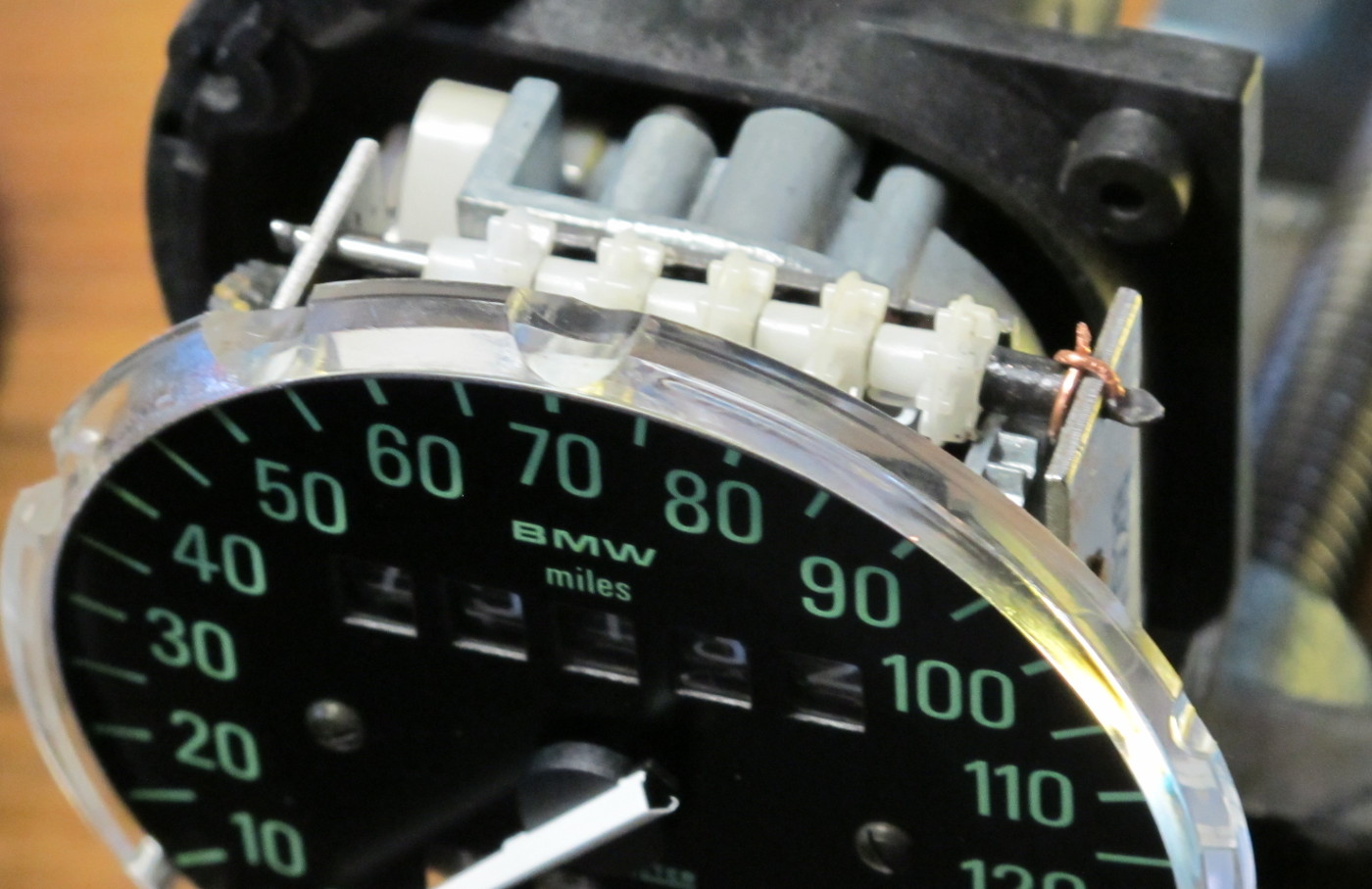 All of the white gears are identical, so I pulled the shaft that they’re on and moved the damage gear from the far right position to the far left position. I then shifted everything, dials and gears, to the right as much as possible so that the far-right gear is over the metal gear. After putting everything back together I left the shaft end in a slightly flattened shape. It doesn’t slide out easily, but it can be slid out with a little bit of pressure.
When I had the gears out I attempted to repair the damaged gear. Using heat, I reshaped the damaged teeth. They’re better, but not perfect. With the less than perfect gear on the far left, it’s not going to spin very often, and if something does go wrong it will be very obvious as the reading will change (or not change) by ten thousand miles.
The reason that the odometer was reading high is that, unless the white gear is over the metal gear, the mile digit is free to spin, and it will. The dials are mounted on a shaft that spins when the bike is moving, and though not fixed to that shaft, there’s enough drag to spin the dial. When the white gear is over the metal gear, the dial can’t move, except when it’s supposed to. That occurs when the notch in the metal gear’s circumference grabs a tooth on the white gear.
I didn’t do anything to prevent the gears from sliding back to the left, so the problem may return. If it does I think I’ll install a small spring on the left side of the shaft to keep things shifted to the right. It’s not obvious to me how everything is supposed to be held in alignment. Friction?
As I don’t know how long the odometer has been broken, I reset it to the mileage that was on the bike when I bought it, plus my best guess at how many miles I’ve put on the bike, which isn’t many. I’ve done a lot of work on the bike and I do want to keep track of how many miles have elapsed since performing that work. There’s no way of knowing how many miles are on this bike, but it’s likely less than 75k.
At some point I expect the odometer to stop working completely — another common problem on these bikes. While working on the odometer I noticed the metal gear slipping a little bit its shaft. This only happed when the white gears weren’t lined up correctly and things weren’t spinning easily. It seems fine now, but if the gear gets any looser on the shaft I’ll have to take things further apart as the speedometer dial will have to be removed to gain access to that part.
Update: 9/14/17 The metal gear did slip, right away. However, I was able to repair the problem WITHOUT removing the speedometer dial as described here. I began by loosening the screw on the left side so that the worm gear could be disengaged. This allows the gears to be spun by hand, which makes it easier to apply epoxy all of the way around the metal gear and shaft. I now believe that the gear was not only slipping, but that it had slid to the right a bit, which is why everything else was loose. So, I pushed the metal gear on the right, back to the left, while pushing in on the gear on the left (the gear which engages the worm drive). This tightened everything up. Next I cleaned the right gear and shaft with alcohol and then, for extra grip, scratched the shaft next to the gear with a small precision screwdriver. Using the same screwdriver I applied JB Weld Hightemp epoxy to the shaft/gear joint, being careful to keep the epoxy away from the plate that the shaft goes through. The end result was almost identical to this picture. I used this particular JB Weld epoxy because it’s a thick putty. It was easy to shape while spinning the gear, and it didn’t run all over the place. So far, so good! The odometer and trip meter agree over the first 100 miles.
 While I had the case apart I also cleaned the frosted glass and replaced both the outer o-ring seal, and the center indicator light seal.
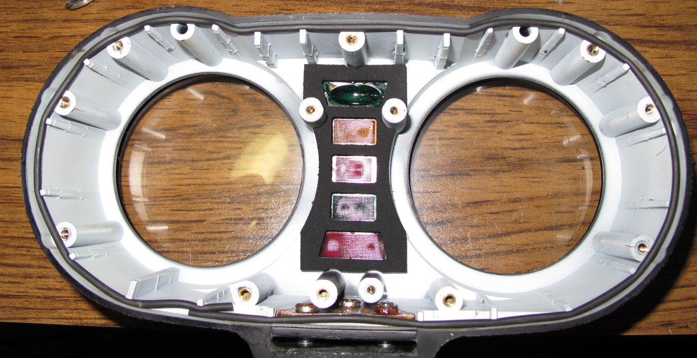 On to the indicator lights.
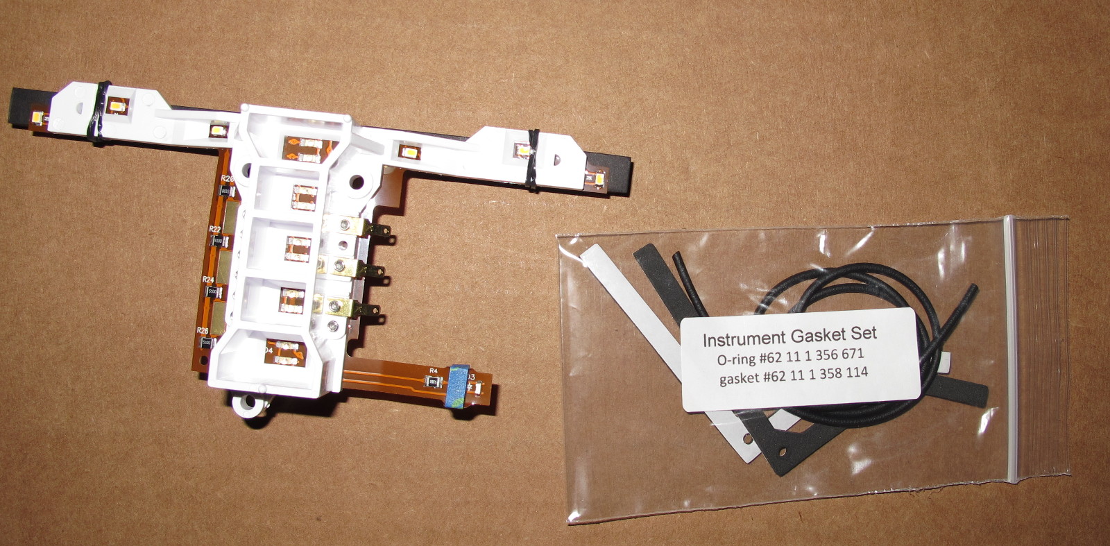
The turn signal indicator didn’t work because a copper foil tab had broken off and gone missing. This is a common problem with this design. I was able to repair this by exposing a bit more of the foil and soldering on three short strips of solder wick. This isn’t the best solution, but I didn’t have any copper tape.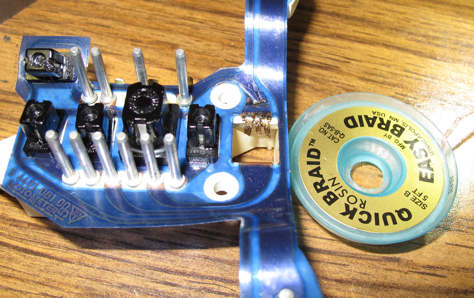 While the repair worked, I’d heard good things about an LED based replacement board from Katdash.com, so I ordered one. As shown below, it comes with new gaskets.
 I’d already replaced the outer o-ring seal, but not the foam seals — those are no longer available from BMW. As you can see, the foam seals that were on the bike had not been carefully installed.
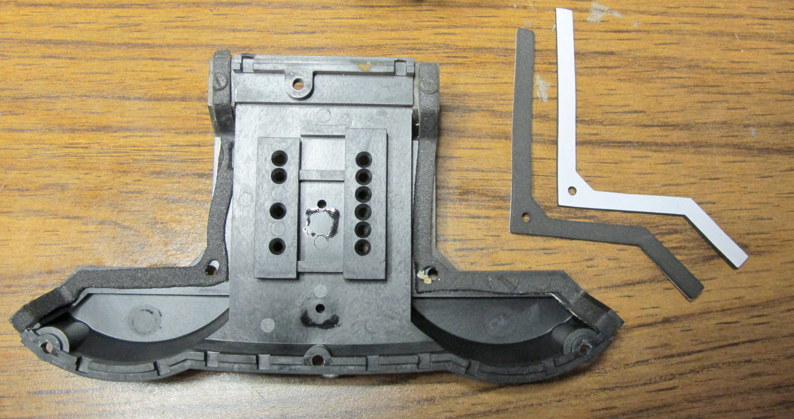 They old seals came off easily and the new Katdash foam seals fit perfectly. I used the shaft of a small screwdriver to help align the hole in the tape with the hole in the plastic as I was installing the new seals.
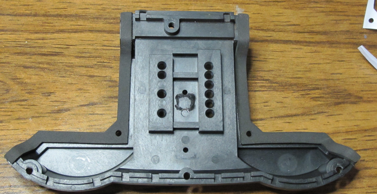
Having replaced every seal, my hope is that the instruments will be less susceptible to moisture. From the design of the instrument pod, I don’t expect it will be waterproof.
Here’s the new LED board after installation. One difference on this board is that the high beam indicator extends much further into the light tube making the high beam indicator very bright — a significant improvement over the old design.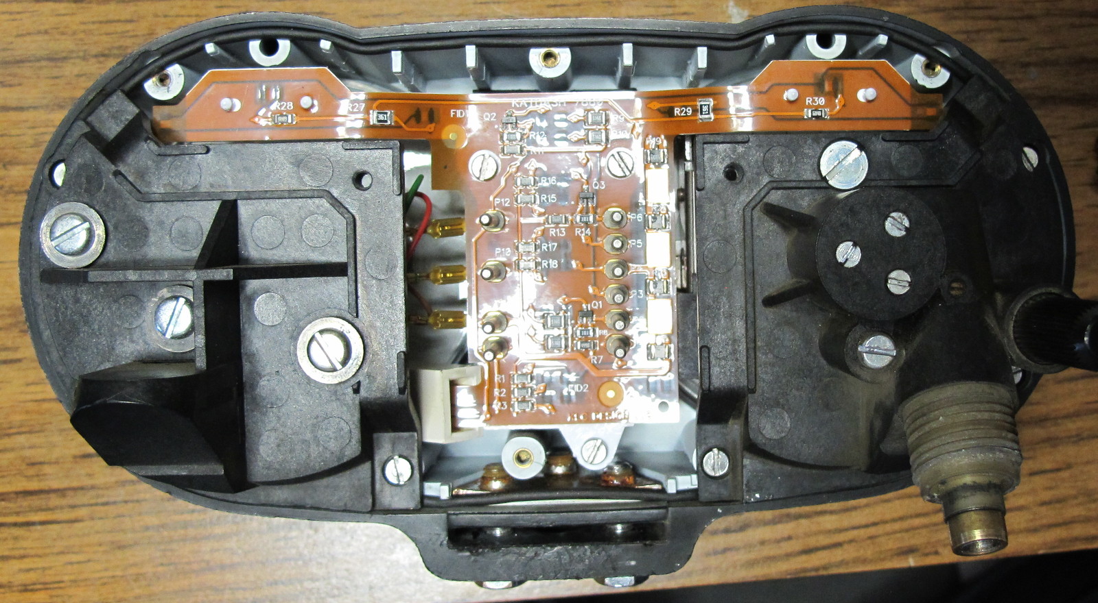 The indicator lights are definitely brighter!
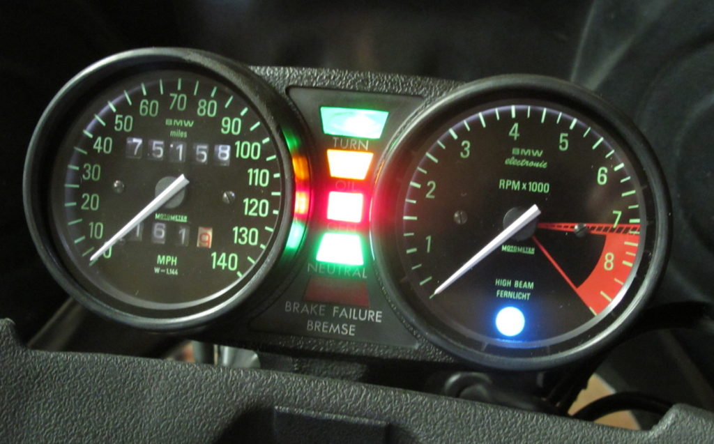
While brighter, the new instrument lights aren’t as warm. The light is cooler, more white than yellow. Still, looks good!