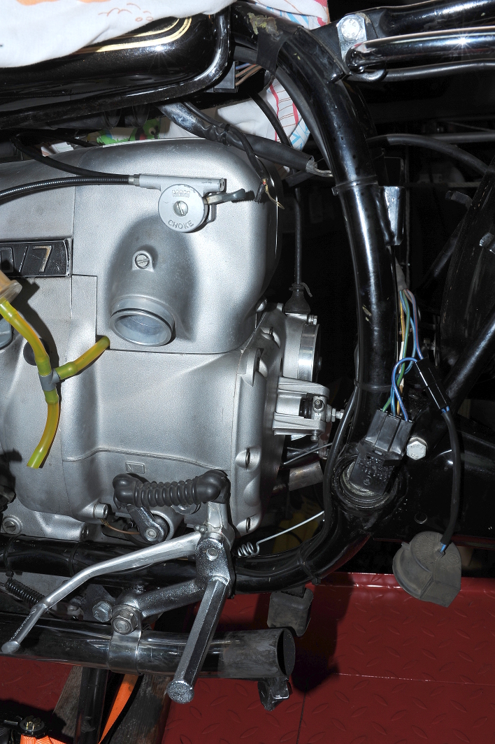
Before installing the transmission I had to address the problem of the oil-leaking neutral switch. This is an apparently common problem, even with new switches. As this switch otherwise seems to work, I’ve attempted to seal it with JB Weld.
There seems to be many variations of switches used on airheads, so the first step is to document this switch so that I know what to buy should I ever need to replace it.
First, it’s normally closed (NC). That is, the switch conducts when the plunger is not depressed.
The washer is 1.8mm thick, as shown here. Its inner diameter is ~12.4. The outer diameter is ~19.9mm.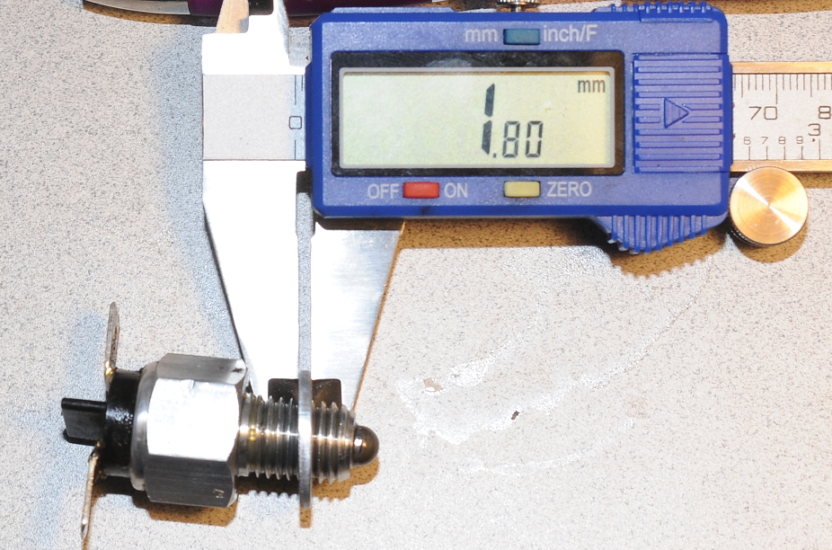
The switch length from the shoulder to the tip is 19.5mm. 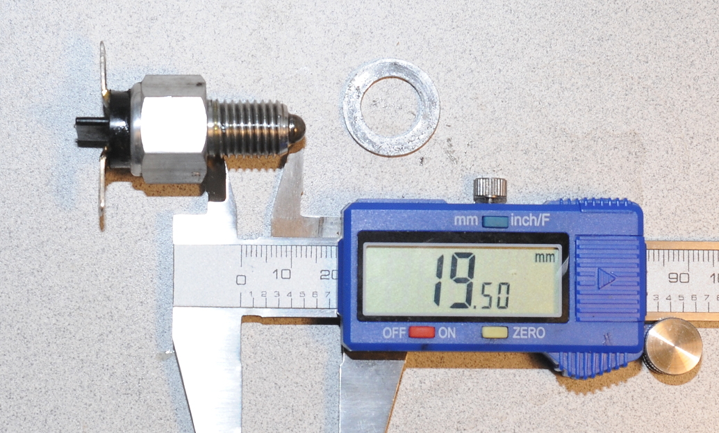
It appears that someone’s already added sealant to the connectors.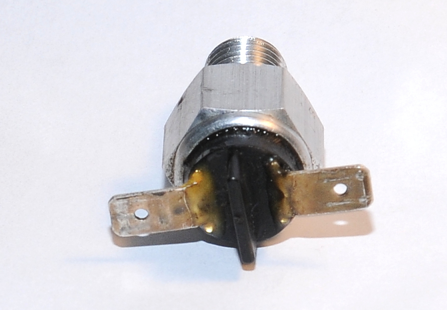
Upon closer inspection, it also appears that the original repair has failed. The sealant has separated from the back side of the connector, and also cracked at the bend. Before seeing the damage, I was tempted to leave the original repair in place. 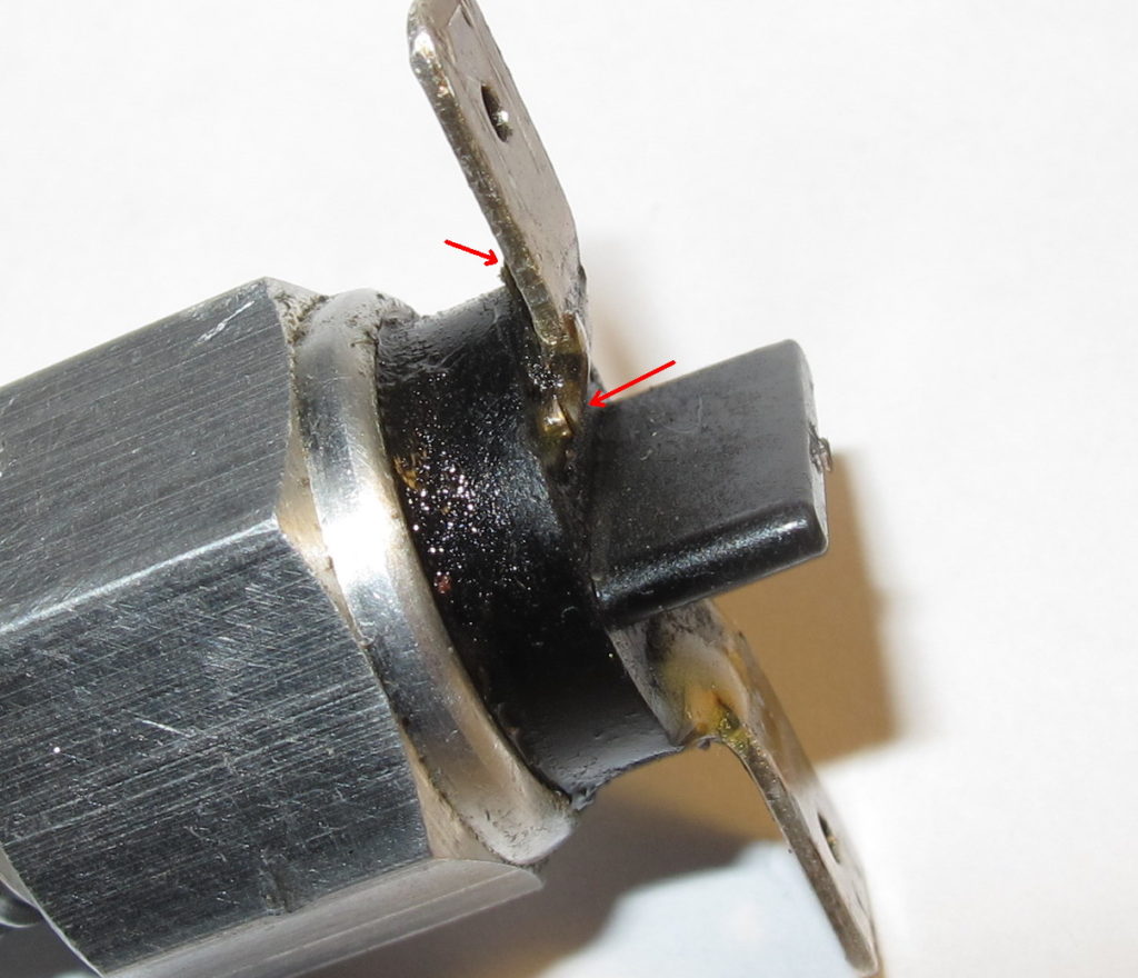
All cleaned up, degreased and after a bit of sanding to roughen things up, ready for epoxy. Using a sharp chisel and a microscope, it was easy to remove the old sealant, whatever it was, without damaging the switch. The connectors are very clean in most places under the old sealant suggesting the sealant was added when the switch was new (so probably not the switch installed at the factory).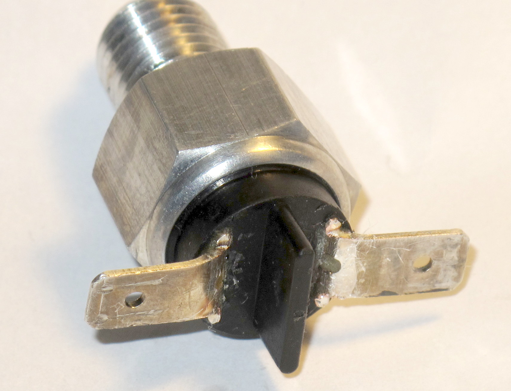
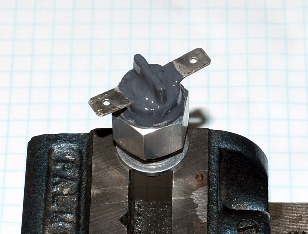
I used JB Weld Original to seal the switch. I first tried RTV, but it shrank while curing and pulled away from the connectors. Others have used JB Weld, so I expect this repair to hold. You’ll no-doubt notice that I’ve sealed not only the connectors, but the crimp joint as well. Oil kept seeping out of that joint while the switch out of the transmission, so I suspect it was the primary source of the oil leak. Using a toothpick I tried to force as much epoxy as I could into the joint. All of the remaining plastic was coated with JB Weld, just for appearance sake.
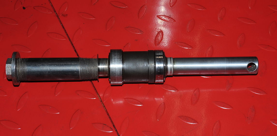
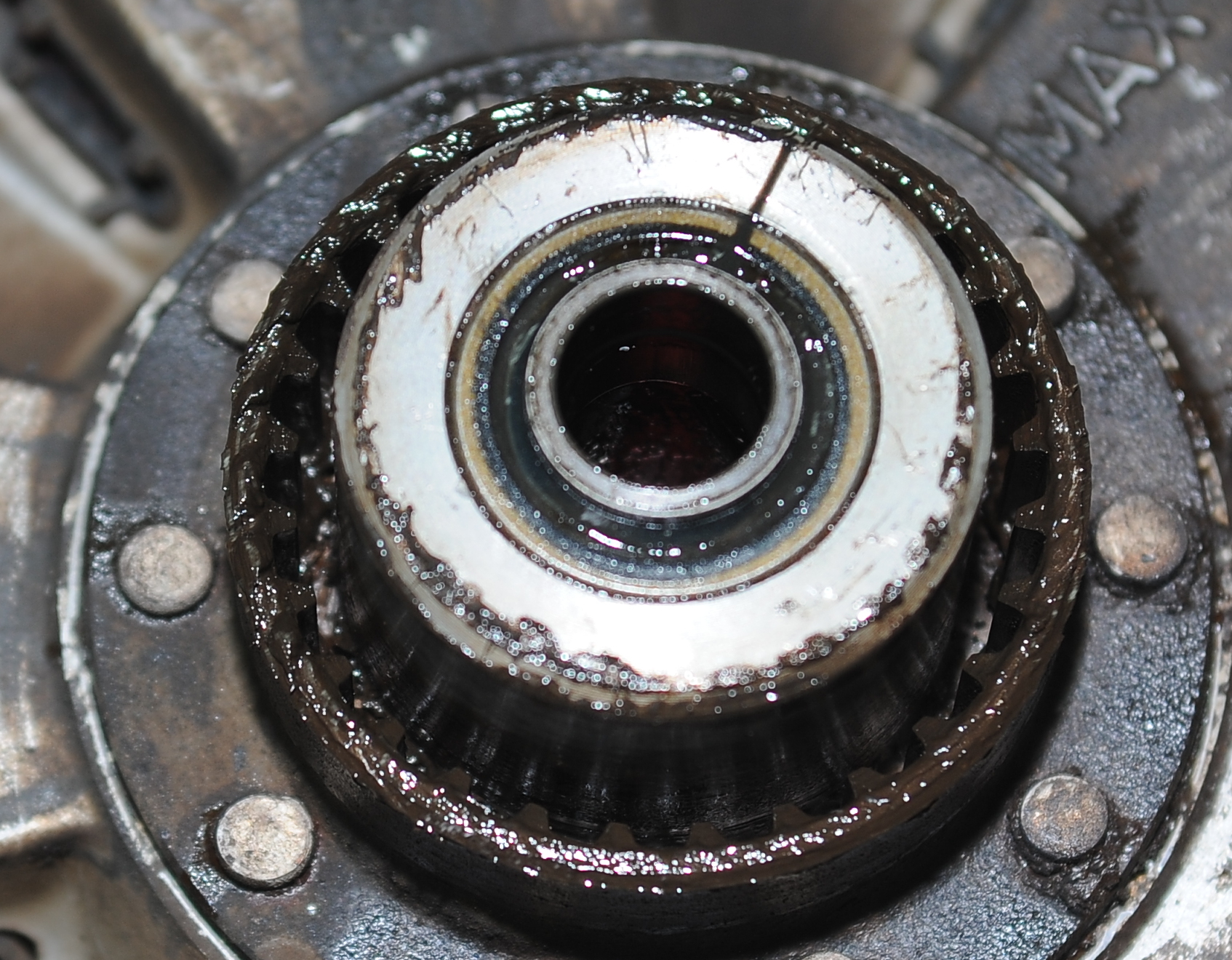
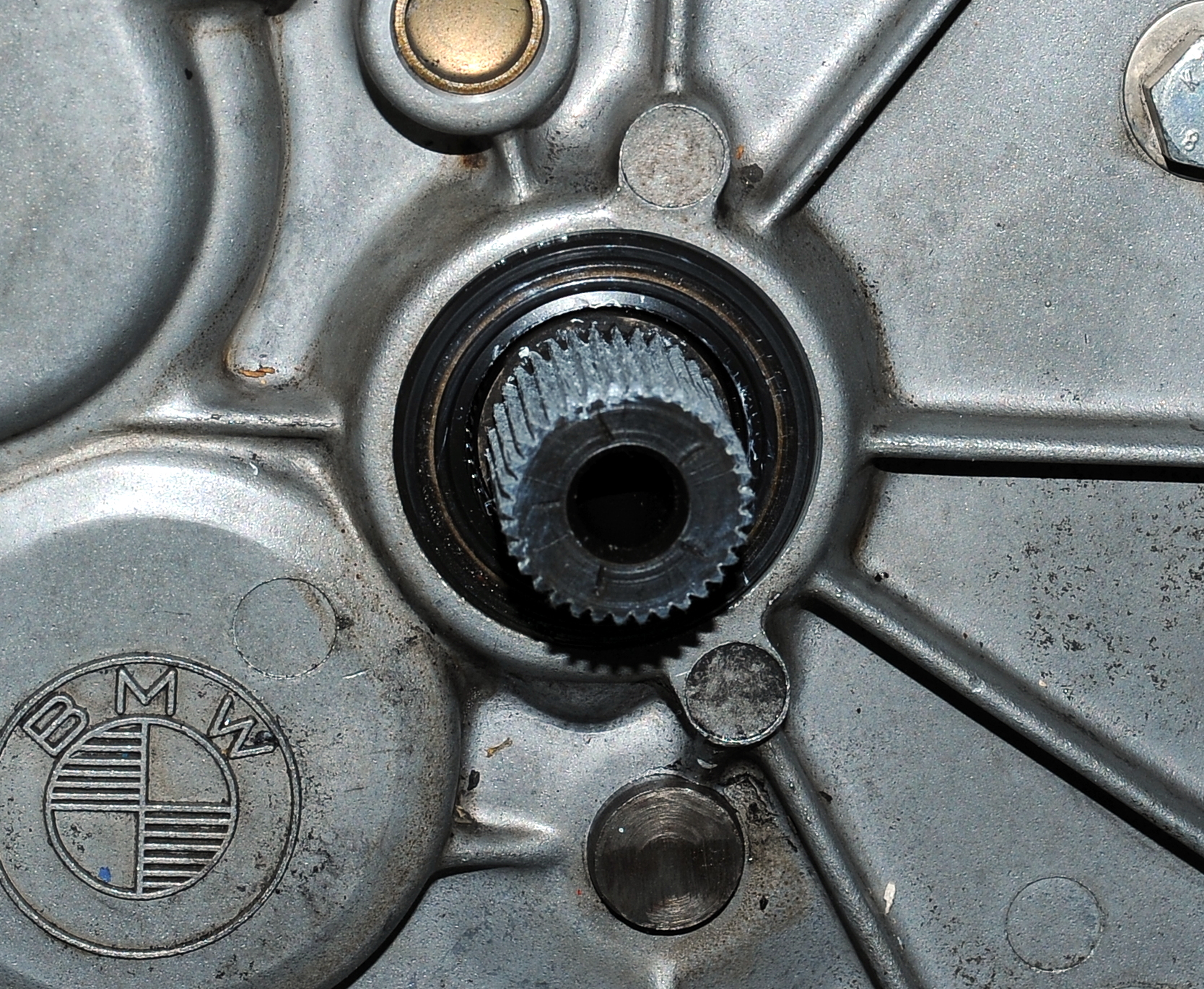
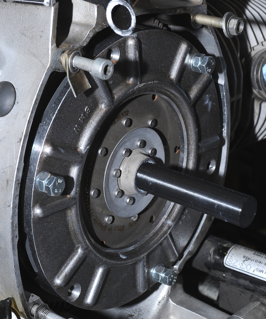
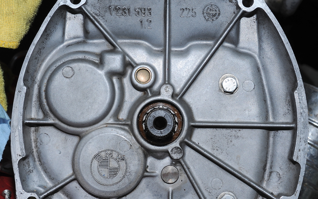
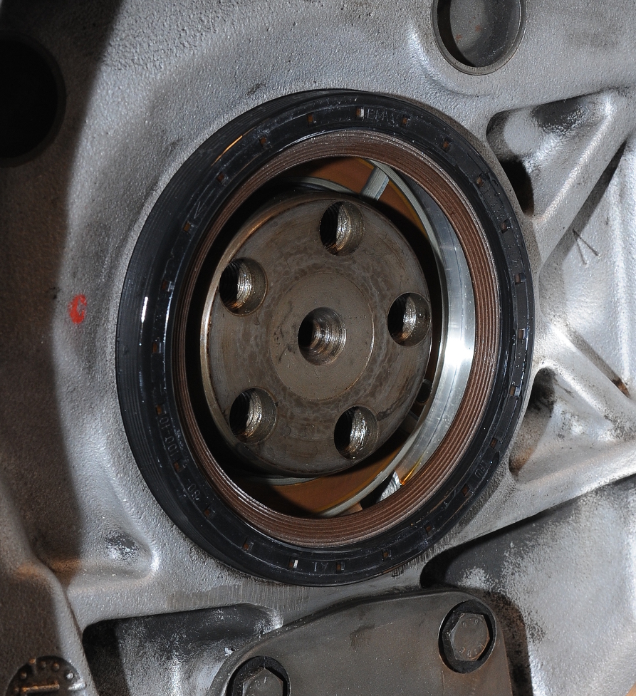
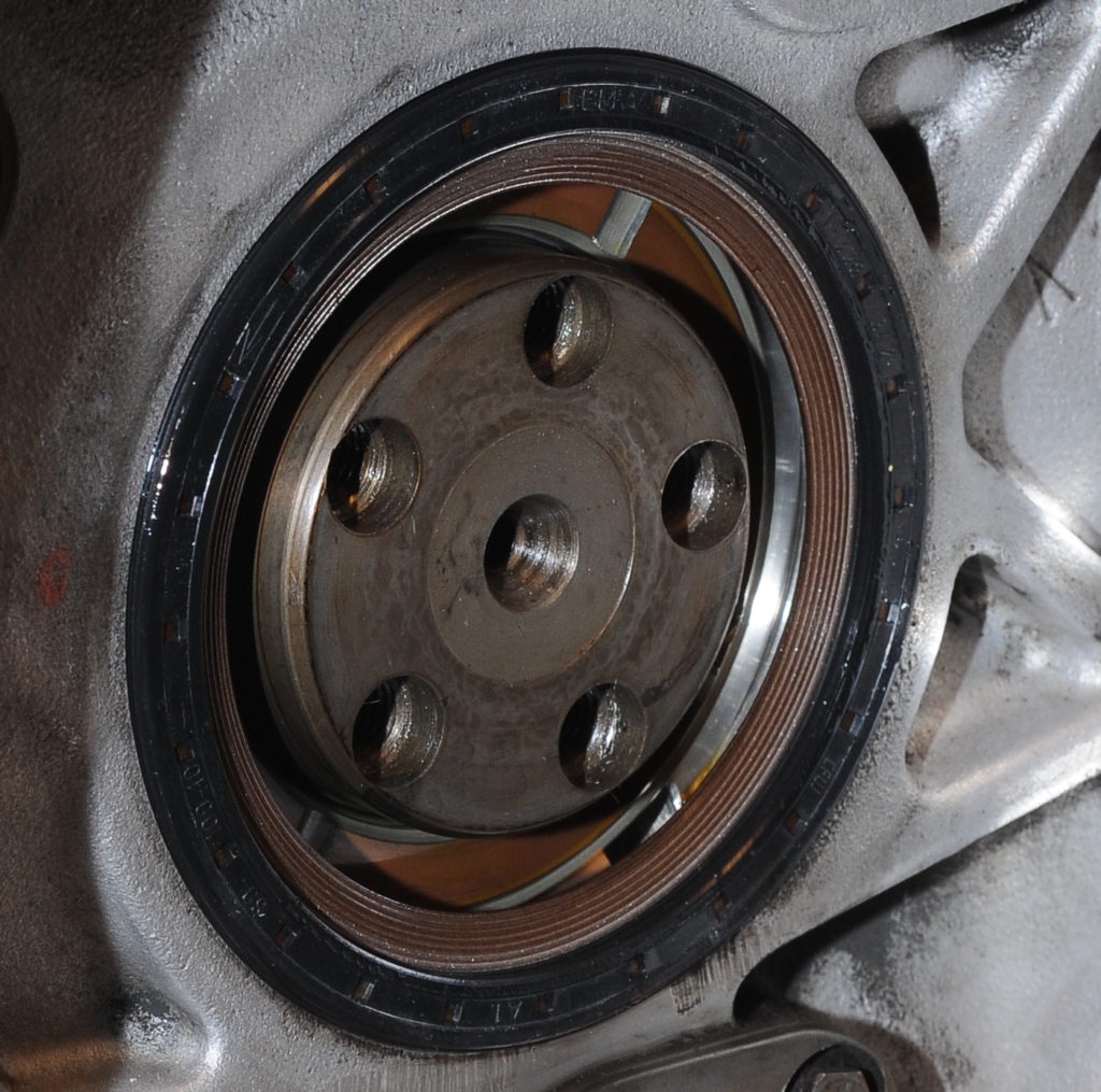
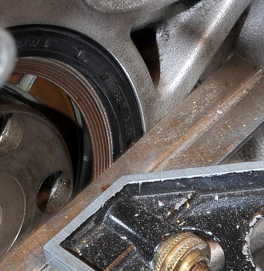
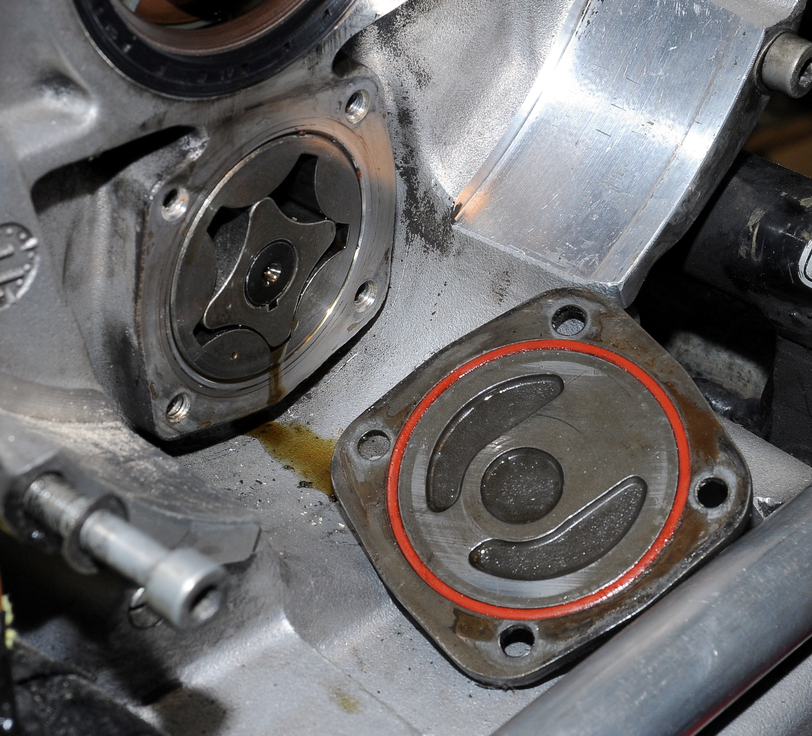
The new transmission input shaft seal went in easily. I didn’t need to make an install tool as I was able to use a 30mm deep socket to drive the seal in. Before installing the seal, I coated it in transmission oil and wrapped electrical tape around the splines to protect the seal as it was being installed. After removing the tape, the shaft splines were lubricated with Staburags NBU30PTM, just like on the clutch disk.

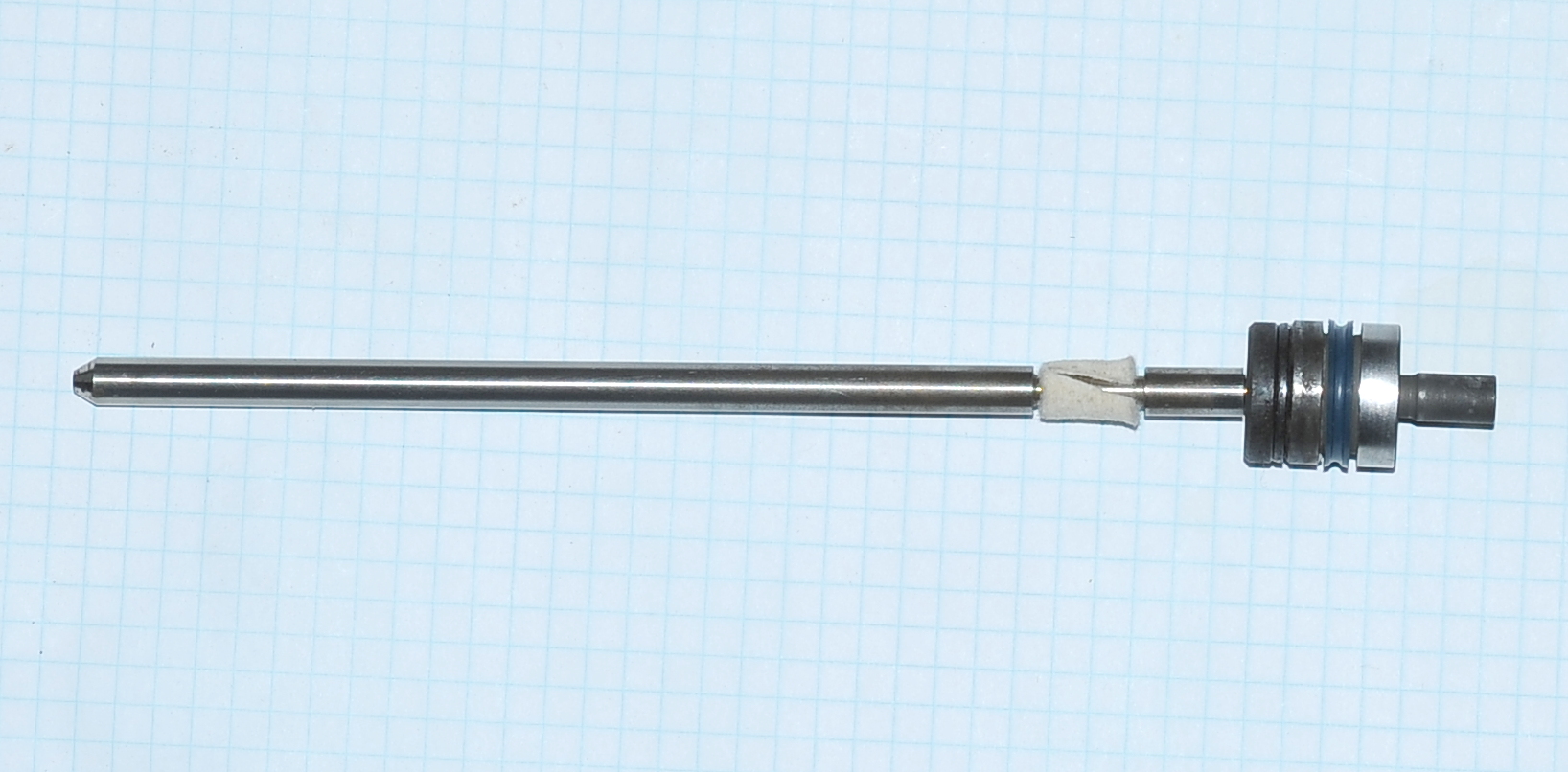
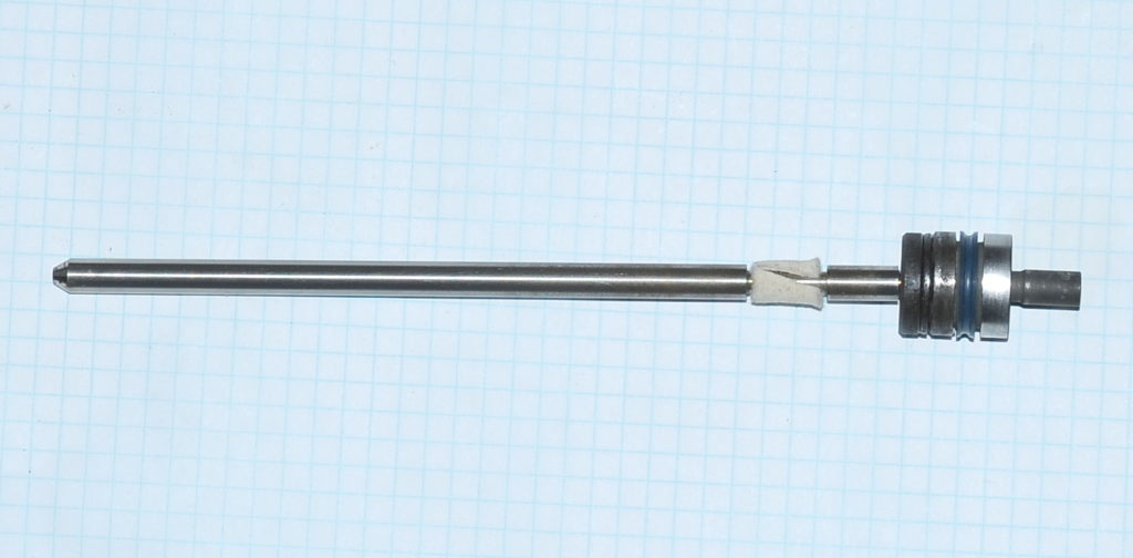
A little bit of the Staburags grease will also be used on the tip of the clutch push rod. Here’s the entire push-rod assembly with the new felt seal, lightly greased throwout bearing and a new piston seal (blue). It took some time to get the rod inserted as the new felt seal would expand and find things to catch on.
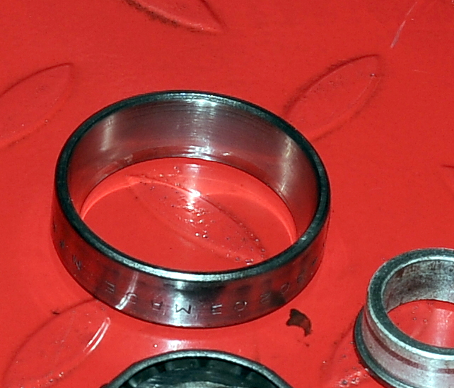
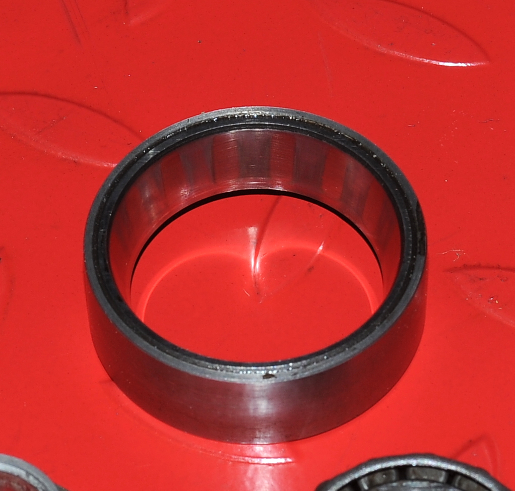
The needle bearing is serviceable but should probably be replaced the next time the transmission is pulled.
 For reference, the picture above contains parts 1-6 in the drawing below.
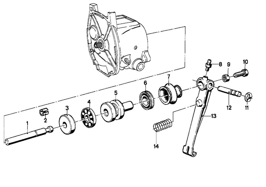 The drawing appears to be incorrect with regards to the rubber boot (7). The narrow end goes over the end of the piston (5) while the wide end fits over a groove in the arm (13). That seems to be the way it should go together, and here’s what it looked like before I took everything apart. I have a new boot to install as the old one was split.
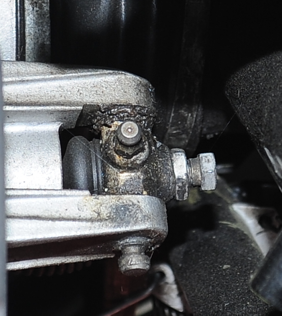
The grease fitting only seems to service the shaft, so I’ll be putting a bit of moly grease where the adjustment bolt (10) pushes against the piston (5).
As soon as the JB Weld cures, the transmission can be installed.
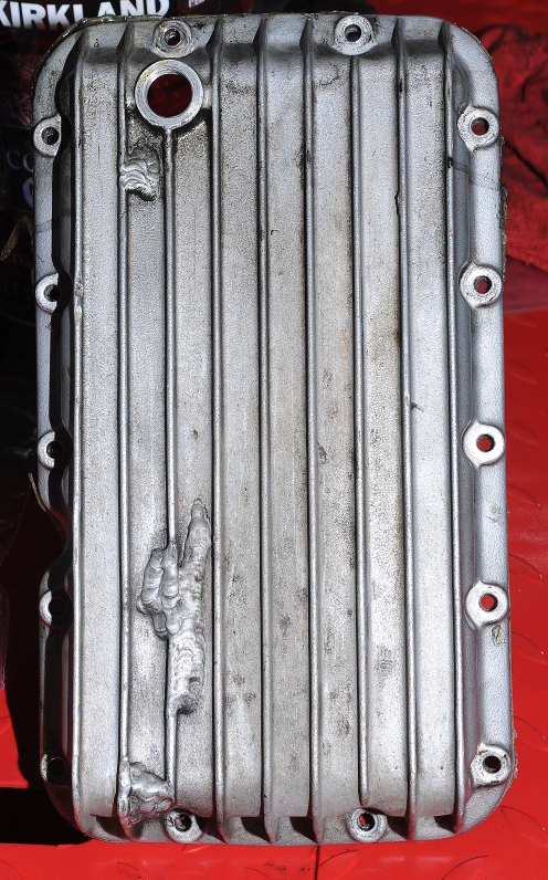
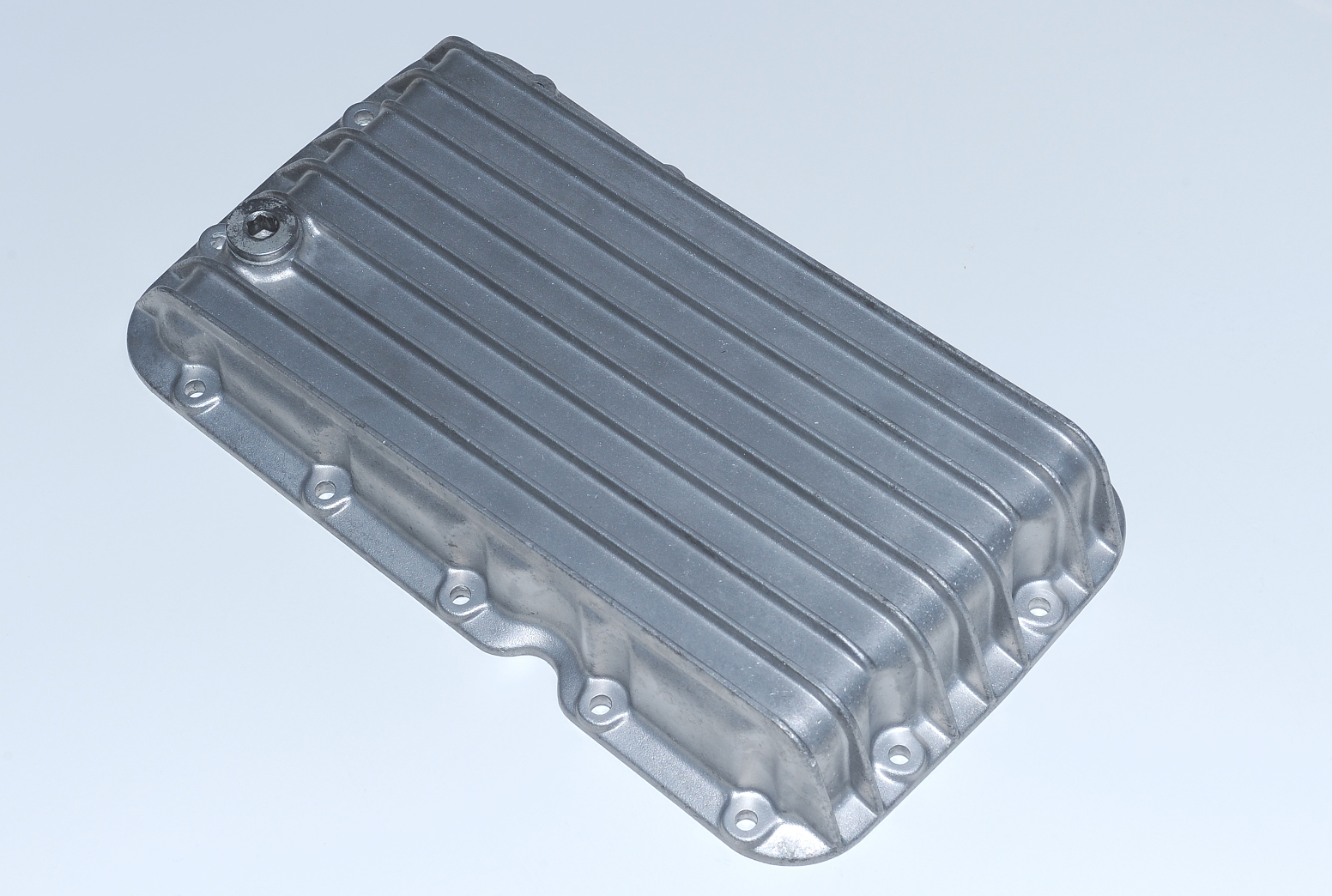 Media blasting removed most of the corrosion that was on the pan. It looks pretty good now, not that you’ll ever see it on the bottom of the engine.
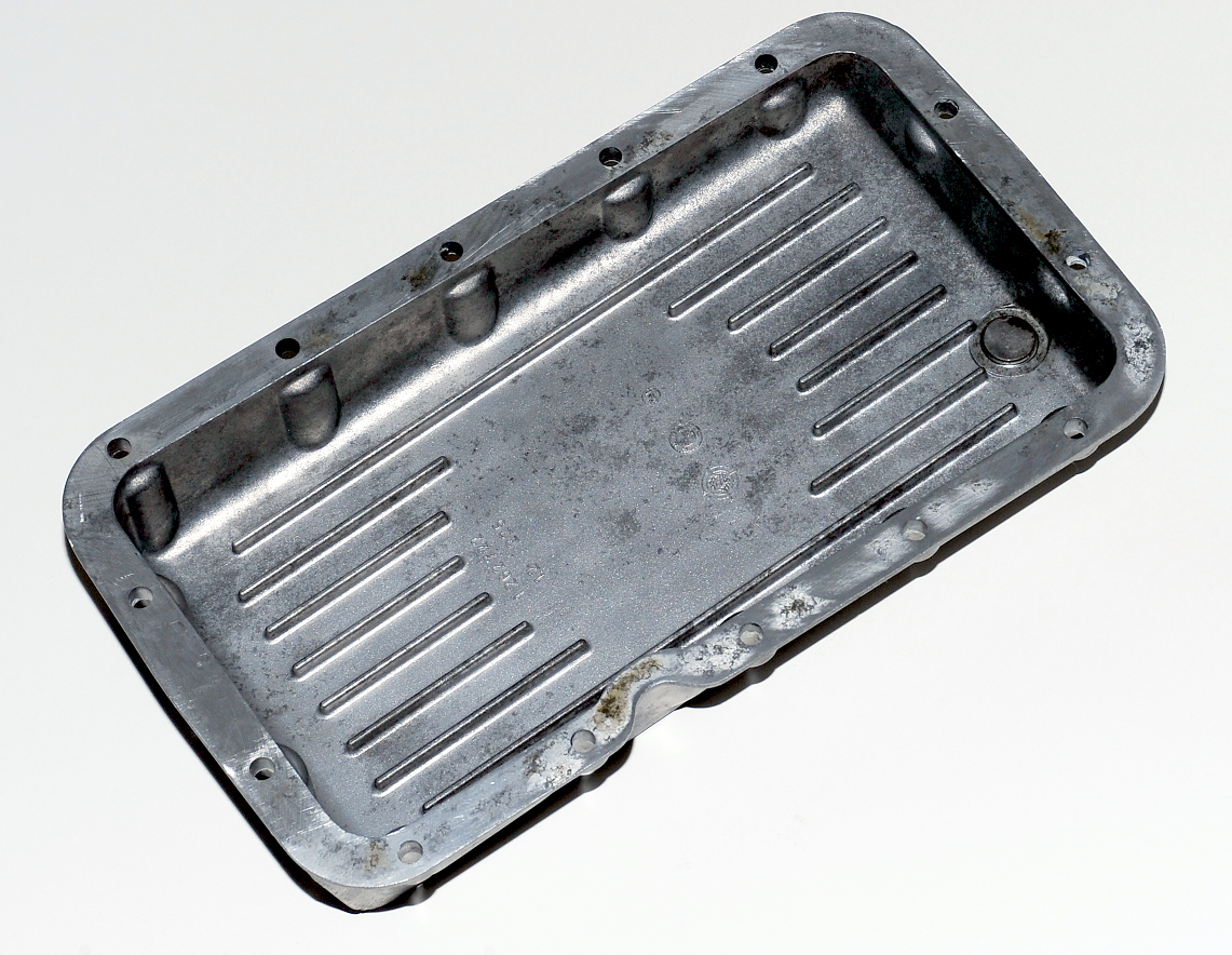 With the new pan ready to go, it’s time to pull the old pan.
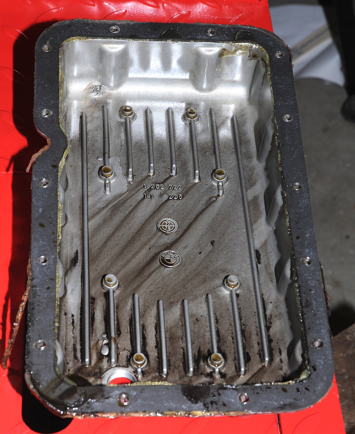
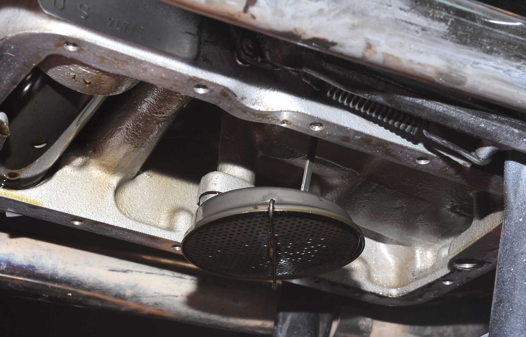 I pulled the screen, cleaned off the oil, and gave it a good inspection. All is good. Here are the parts all ready to be installed.
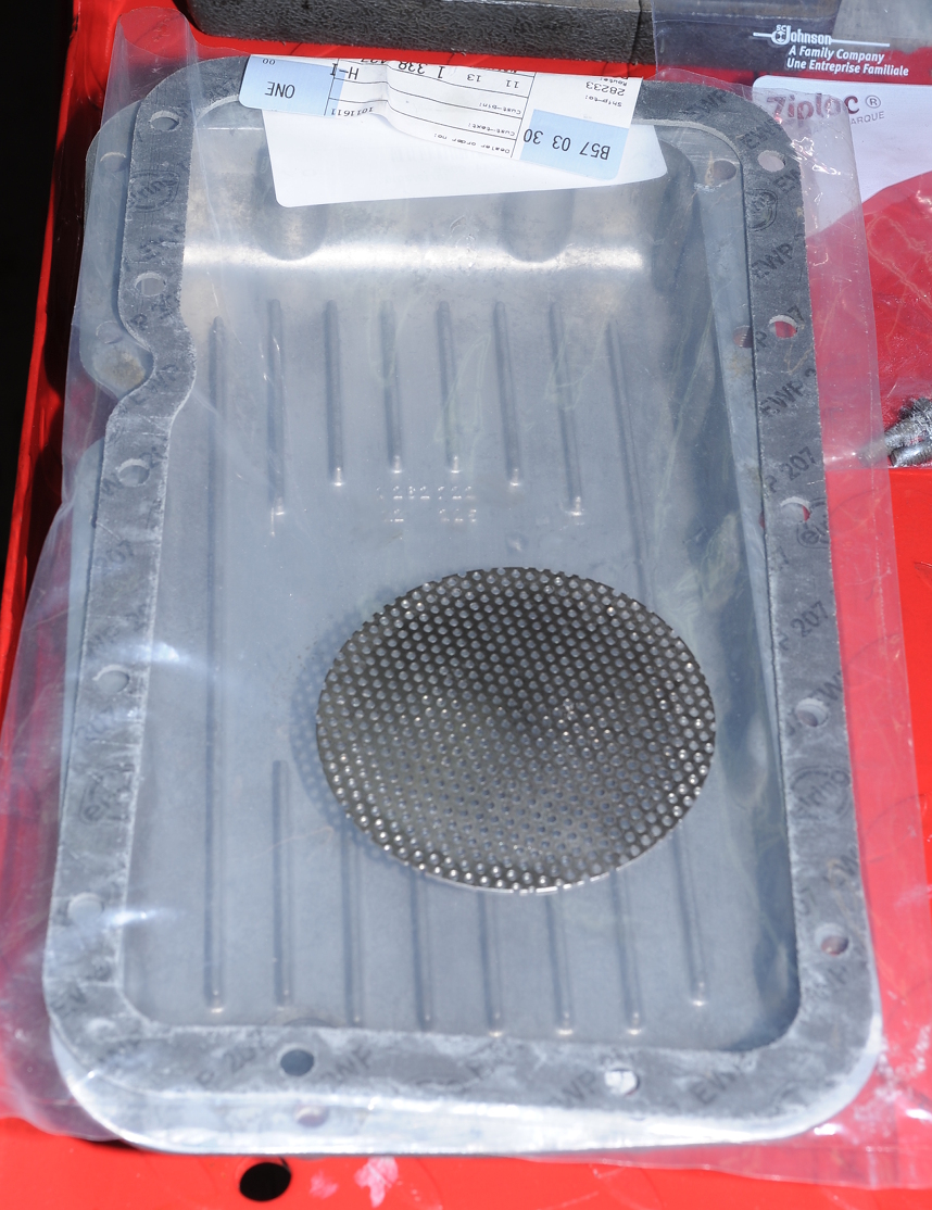
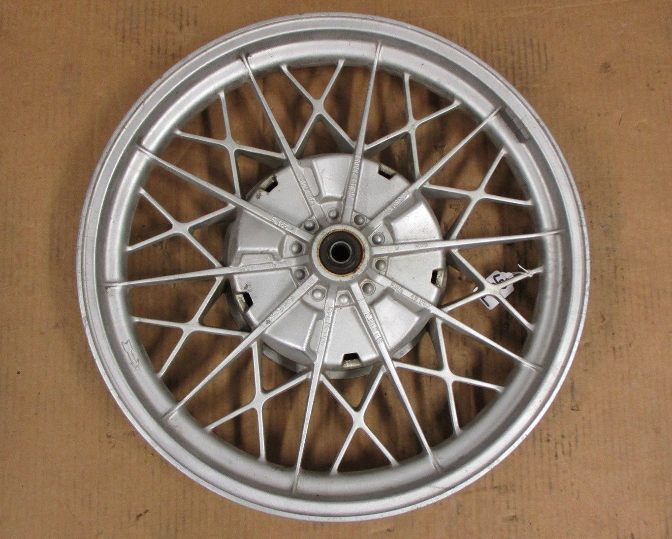
 As soon as the new wheel arrives I’ll get to start over on splines and bearings. Yeah!