Cleaning the transmission while waiting for parts

As I’m still waiting for a few parts to arrive before putting everything back together (minus the final drive) I decided to clean up the transmission tonight.  One of the parts I’m waiting for is the input shaft seal.  I’m also waiting for new flywheel bolts.

The transmission looks a lot better now!  The black seal around the splined input shaft is the one that will be replaced, along with the main rear seal on the crankshaft, the felt seal on the clutch pushrod and seal on the pushrod piston.  I hope that solves all of the leaking problems!

The transmission oil has been drained, so I’m going to pull the neutral switch and see if I can seal the switch with epoxy, something similar to what’s described here.

Most if this clutch dust and oil cleaned up easily with brake cleaner and/or kerosene.  For some reason the bottom center section was hard to clean, the crud didn’t want to dissolve.

Removing the Rear Main Seal

The rear main seal is out.  Removing it wasn’t too difficult.

Here’s a side-by-side of the old seal (left) and the new teflon seal.   They’re both exactly the same size, though the teflon seal is supposed to be installed flush.  The seals are 100mm in diameter and 10mm high.   All of the pictures in this blog are high resolution, click on the picture for higher resolution.


To remove the old seal I drilled a hole in the seal at 9 o’clock and inserted a drywall screw with a fender washer on the end.  It was a longer drywall screw,  the screw head needed to be about the same height as the edge of the case.   I also drilled slowly, and inserted a rag to keep the metal filings from flying into the engine.  While the seal is rubber (or plastic) on the outside, I was drilling into metal.

I didn’t have a slide hammer or fancy seal puller, but I did have a small wonder bar (flat pry bar).  I placed a block of wood on the edge of the engine case to use as a fulcrum.  While applying pressure to the pry bar, I tapped on it with a hammer — not too hard.  The seal slowly began to rise and then quickly came out.

Unfortunately I won’t be installing the new seal into the engine today.  The dealer I bought this from shipped all of the parts as shown in this next photo. All of the seals were in the same bag as sharp-edged objects such as drive-shaft boot clamps (not visible) clips, clutch bolts and drive-shaft bolts.  They were also subject to the weight of the clutch components sliding around in the same box.

The dealer is supposed to be sending me a new seals ASAP.  I don’t want to risk using these unless I’m forced to.

The main seal was deformed when I pulled it out of the bag as shown in the next picture at 12 o’clock.  Now this teflon is flexible, and generally tough, but that’s not the point.  The seal could have been over-extended and there may be small scratches that accelerate wear.  It just sad that the person doing the packing couldn’t take the time to protect these expensive parts from damage during shipping.  

The clutch seal (for clutch rod piston) had a couple of notches taken out of the edges (red arrow for one).   I can’t be sure that this damage happened during shipping, but with the part in the bag with lots of sharp-edged products, there’s every possibility that it did.   

Pulling the flywheel

The flywheel is out.  As you can see, things are very dirty, but the rear main seal, if leaking at all, is leaking very slowly.   The new seal is on its way, so I’ll probably install it anyway.  The new seals are supposed to fit flush with the case.  This one sits proud by about 2mm.  I’ve also ordered a new seal for the oil pump cover at the bottom.

Looking much better after cleaning.  Notice the ’77 date stamp in the lower, left corner.

Here’s a closeup of the rear main seal.

The flywheel is in very good condition.  You can see some minor wear on the teeth, still, not bad for 75k miles.

The main seal seals against the center hub.  The hub is discolored, but is very smooth — nothing rough or sharp to damage the seal.

The timing marks will show up a little better with some white paint.  The OT mark is top-dead center.

Next up is cleaning up the transmission and,  after I receive all of the new parts, main seal and flywheel installation.

3D Printed Airhead Tools

It turns out that plastic tools are perfectly fine for some tasks.  With the advent of low-cost 3d printers I think it makes sense to explore 3D printing as a way of fabricating specialized tools for our airheads.

So far I’ve built two tools: a clutch alignment tool, and a tool to keep the crank in place while removing the flywheel.   For more information about these tools, including the STL files visit my tools page.

Clutch Alignment Tool
Tool to keep crankshaft from moving when working on the flywheel

The next tool I hope to design is a rear-main seal installation tool.

Pulling the clutch

If you’re interested in how this clutch works, visit my tutorial Airhead Clutches Explained .

To remove the clutch I needed three long 8mm fine-thread bolts, nuts, and washers so that I could release the pressure without damaging anything.  After a quick trip to Ace Hardware I was in business.  I replaced three of the original bolts with the longer bolts with the nut and washer set to approximate the length of the original bolts.  I then removed the remaining original bolts, and evenly backed off the nuts, while keeping the bolt from turning, until there wasn’t any more pressure from the spring.

Except for being worn to within 0.1-0.2 mm of the minimums, the clutch components look really good.  There are no signs of overheating or any other evidence of abuse.  I measured the friction plate thickness at 4.6mm (new thickness is 6mm).  Wear limits are 4.4 or 4.5mm depending on where you look.

I could probably continue to use this clutch spring, there’s not a lot of wear, but the spring is relatively cheap to replace, and it’s probably been under tension for 40 years.  In fact I could probably just order the friction plate.  But since new OEM parts are available now, and they might not be in five years, I’ve ordered a kit from Bob’s BMW that includes all new parts.  Once those are installed, the bike the bike should be good for another 75k miles, at least in terms of the clutch components.

The flywheel looks good, but there’s moisture which suggest that I also have a rear-main seal leak.  So that’s going to be replaced as well.  In this shot it’s easy to see how the timing inspection cover (next to the oil fill) lines up with the flywheel.  When I get the flywheel off, I’ll repaint the timing marks to make them easier to see.

Good news, this bike has the newer oil pump cover with hex bolts instead of Phillips-head screws.   I haven’t inspected all of the starter gear teeth yet — I’ll do that when I pull the flywheel — but so far they all look good.

Next step, pull the flywheel.

Pulling the carbs, airbox and transmission

To pull the transmission, I have to first remove the carbs (or at least move them out of the way) and remove the airbox.  After seeing the crud floating around in the bowels and the discoloration on the floats I decided to drain the carbs and remove them.  I’ll rebuild them before putting them back on the bike.  As you can see, they aren’t super bad, but they do need cleaning.

The discolored floats probably indicate that the floats are heavier than the should be, so they’ll be replaced.

Now here’s a bit of German engineering (not!)  If you look at the airbox right cover, you’ll notice that the cover is held in place by a spring on the bottom, and a bolt on the bottom left corner.   It looks like you should be able to loosen the nut and slide the cover off.  But look at the crankcase ventilation hose, it runs through the case and against the starter cover, effectively preventing you from sliding the case off.  I had to completely remove the nut so that I could slide the cover back, and off the hose before I could remove it.   That turned out to be OK though as that’s one of the four bolts securing the transmission to the engine; I had to remove it anyway.

This is the clutch bearing and pushrod with the clutch lever and associated parts removed.

The transmission is only held to the engine with four easy-to-remove bolts.  It came out very easy, but only after I removed the top two nuts holding the battery tray, which allowed the battery tray to tilt back slightly giving me more room to slide the tranny out the left side of the bike.  Here it is.  It looks like the input shaft seal is leaking, so that will get replaced.

The bottom of the transmission is dirty, but looks to be in good shape.  Here it’s easy to see the leaky neutral switch.  Although, the dirt pattern suggests that the oil might also be from the leaky input shaft seal.

The really good news is that the input shaft splines are in very good condition.  Here they are after I cleaned them up a bit.  They don’t show any signs of wear or corrosion.  The tip of the clutch pushrod looks fine as well.

I won’t know the condition of the clutch until I pull it and I don’t yet have the tools I need to do that.  While dirty from clutch dust, there’s no evidence that the rear-main seal is leaking.  I’ll probably replace it anyway, since I’m pulling the clutch.  The arrow points to a loose washer I found at the bottom of the case.  It was lightly held in place by the grime.  In this picture you can see from the frame tag that the bike was built in March of 1978.  I couldn’t see that with the transmission in place.

I found this interesting “mod” today.  It looks like someone added a spring to keep one of the center stand springs from rattling.  I’ve removed that mod for now, but have kept the spring in case I can’t figure out something better.

Pulling the rear brakes, final drive and swing arm

Today I pulled the swing arm.  It was pretty easy to do. Most of the effort went into cleaning the brake grime off of the final drive.  Here’s the before:

Now, here’s the final drive with the brake shoes removed, and after a bit of cleaning; recipe one part brake cleaner, five parts elbow grease.  I did this cleaning before removing the final drive because it was easy to put a pan underneath to catch the brake cleaner as it ran off.  I used an acid brush to scrub all of the nooks and crannies.

To pull the swing arm I had to do the following.

  1. Put the rear tire back on.
  2. Take the clamps off the drive boot and slide the boot back.  The clamps come in two parts, the part that goes around, and a very short piece that fits under the gap between the two ends.  I discovered this when the short piece fell out and I had know idea where it had come from, or even what it was.  I thought it fell out of the boot.
  3. While keeping the tire from rotating, Remove the four 12pt 10mm bolts securing the shaft to the transmission.  Rather than use the engine or the brakes, I just stuck a piece of wood between the spokes and let it push against the swing arm.  These are one-time use bolts, so I’ll have to order some new ones.
  4. Remove the rear tire and axle.
  5. Bungee the swing arm to keep it from falling and remove the shocks.
  6. Remove the final drive (don’t need to do this just to pull the swing arm)
  7. Remove the swing arm pivot bolt dust caps and remove the swing arm pivot bolts (had to grind down my 27mm socket before I could get the socket in far enough to get on the locking nuts).

At this point, I thought I’d be able to pull the swing arm out, but I was catching on something.  At first I thought it was the brake switch, then I discovered that  I had neglected to remove the bailing wire running between the swing arm and the center stand.  I don’t remember reading about that step!  I’m guessing someone put it there when the were reinstalling the swing arm.

Here’s the rear brake pedal and switch.  I’m not sure what the hose is.  It seems to run up under the gas tank.    Water drain?   Here you can see the bailing wire attached to the center stand, and the extra backing nuts on the bolts that hold the muffler.

Anyway,  getting back to the swing arm,  as you can see in the next three pictures, everything looks really good.

Here’s the transmission output.   It looks pretty good too, but the clutch lever is pretty dirty.  Probably from greasing, but possibly from a input or rear-main shaft seal.  Oil could be following the clutch push rod.  We’ll know as soon as I pull the transmission.

I did notice one other task that I need to add to the list.  There’s a bit of rust on the battery tray.  Also, while the rubber supporting the battery tray isn’t cracked, is is pretty hard.  So, when I pull the tray to repaint, I may also replace that rubber if it’s not too expensive.

Next step, pull the transmission.


Conversation with JD Stang @ Beemerbits.com

In my search for headlight parts I discovered beemerbits.com in Tuscon, AZ which lead to a long and pleasant conversation with ownder JD Stang.  JD really seems to know his stuff when it comes to airheads.   I learned a lot.

First, I knew that there had been a recall on the snowflake wheels, as they’re called, but hadn’t yet taken the time to determine if I had the newer wheels.  JD pointed out the webbing on my wheel and confirmed that they were.  According to him, the only people who had problems with the original wheels were cops who tended to run over curbs more than the rest of us.  There are some great pictures of new vs old and broken wheels and the original recall notice here.   I have to say that in those pictures, the new wheels seem to have more substantial webbing than on my bike.  So, just to be sure, I checked the casting date (5/84); this is a good wheel.

The second thing I learned from JD is that my Bing carbs aren’t the most desirable.  In his words, nobody swaps out their carbs for what I have on my bike.  He called them flat-tops and said they were only used a couple of years.  He suggested that if I ever have problems with them that I might want to swap out with carbs from either earlier, or later models.   I think as long as I can keep these working, as they have for almost 40 years,  I’m inclined to keep them on the bike to keep it as original as possible.  It might be kind of hard to find other carbs that look as clean as these.  It seems that full rebuild kits are still available, so I may have to order a set for backup, or to install if I discover that the bike could run better.

JD saw the picture of the oil pan damage and said he could sell me one that wasn’t damaged for $20.   That was a no-brainer, so I added that to my order for a used headlight bucket and mounting ears.  He told me that when I install the pan, in addition to putting sealant around each bolt hole, that I should also add sealant to the bolts to prevent oil leaks.   Something about bolts running through oil passages.  I’ll have to research that some more.

Day One: Muffler and Rear wheel removal

As I expect this project to take a while,  and I wanted it to be fun,  I splurged and purchased a 1000lb motorcycle lift from  Harbor Freight Tools.  It was on sale for $329. It only took a few minutes to assemble the lift which came mostly assembled in a huge, and very heavy wooden crate.  I took the windshield and right mirror off to allow me to run the table up to its highest position.

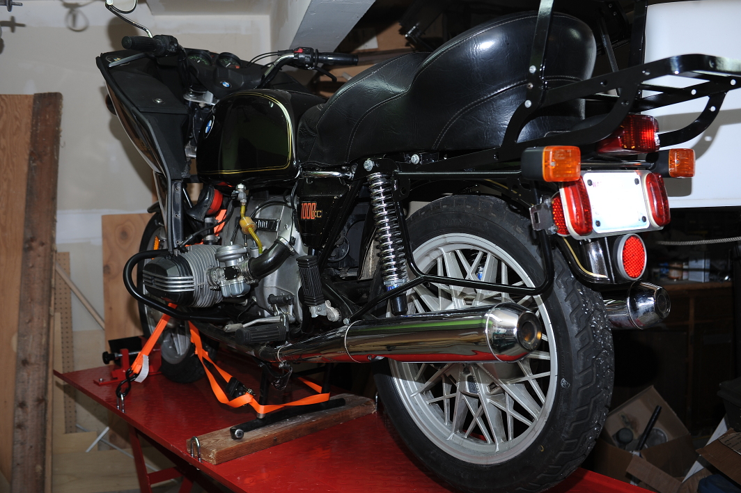
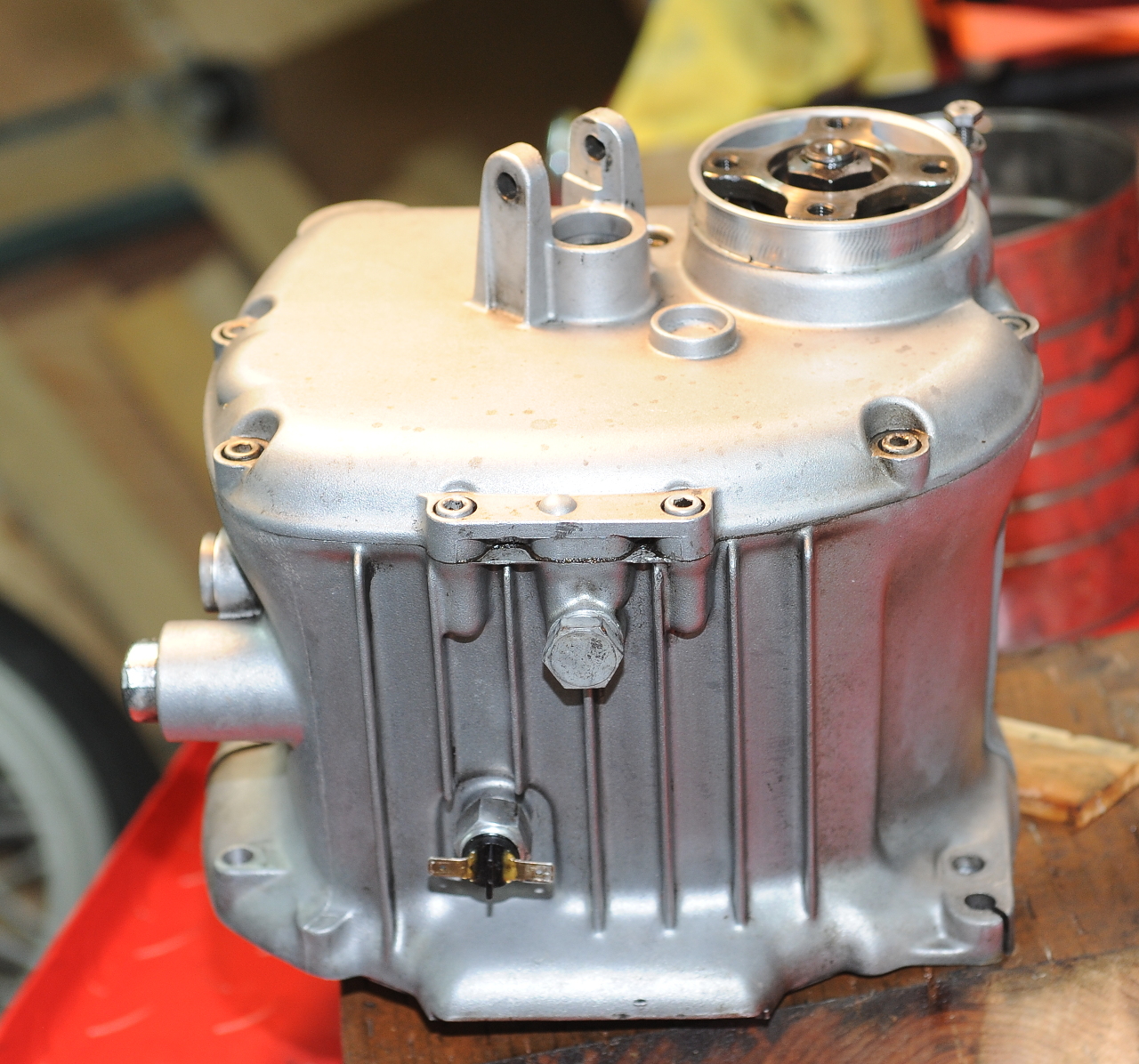
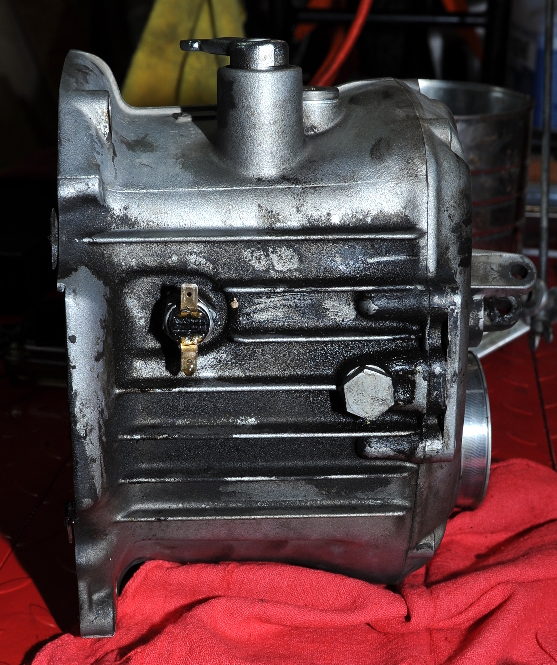
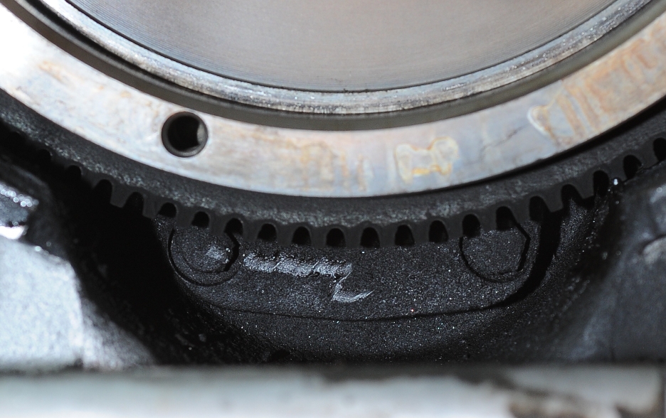
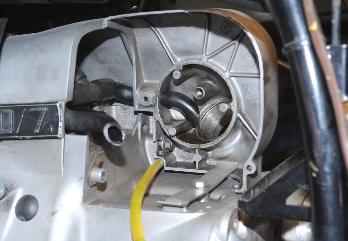
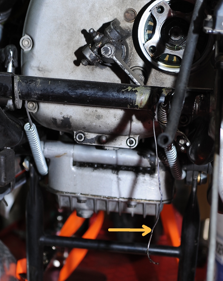
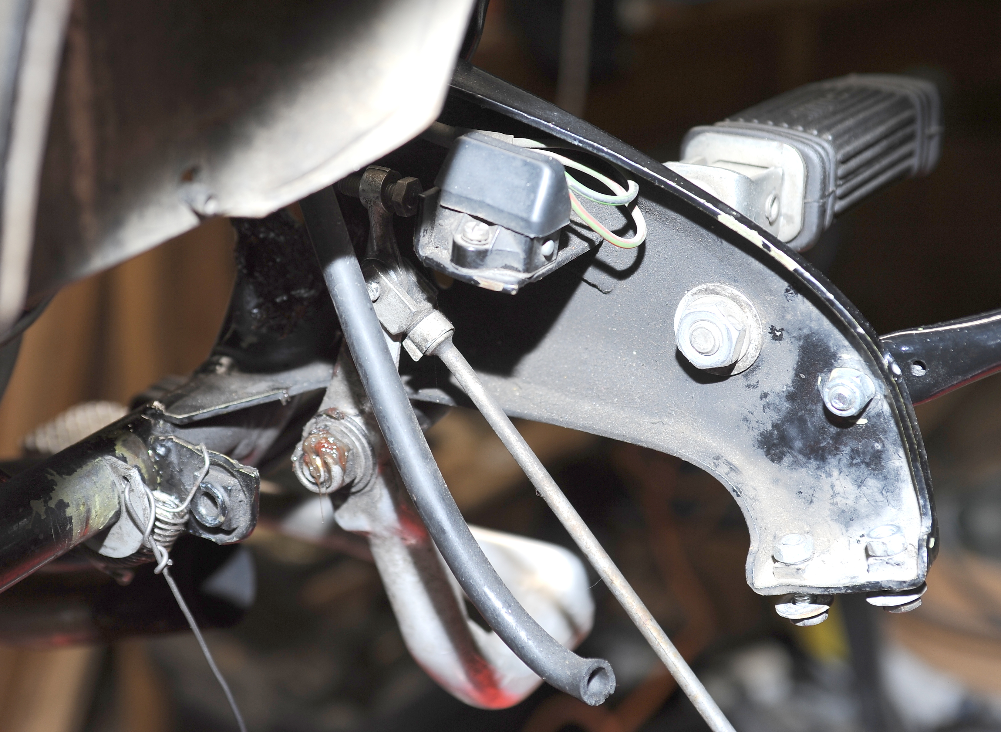
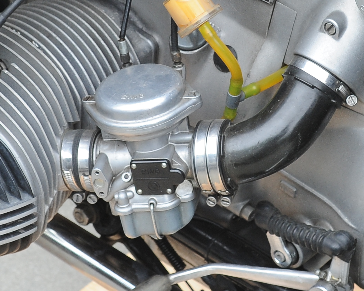
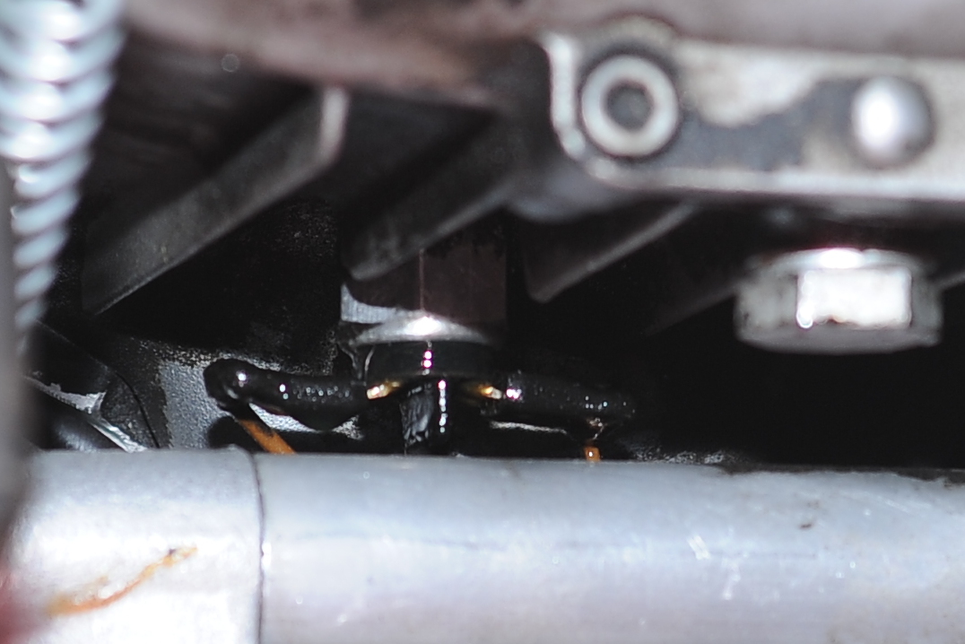
OK first new task discovered, replace the leaky neutral switch.  See the drop of transmission oil on the left terminal?

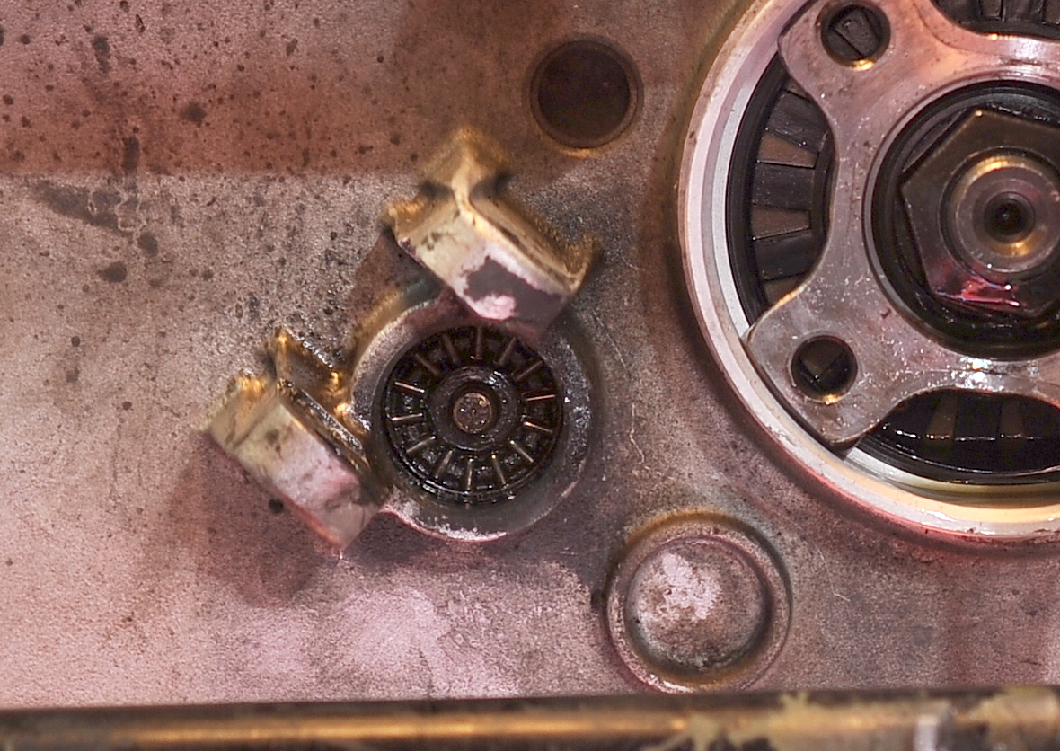
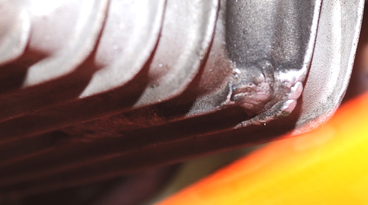
I spotted this oil-pan damage and repair before I bought the bike.  When I get around to pulling the pan, I may try and make to improve on the repair.  There are two spots with damage.

My first task was to remove the mufflers.  They came off nice and easy, though I did discover that one of the captive nuts on the right muffler bracket (frame side) had stripped, so someone added 10mm nuts backing the captive nuts on three of the four bolts.  I’ll probably leave that solution as-is.

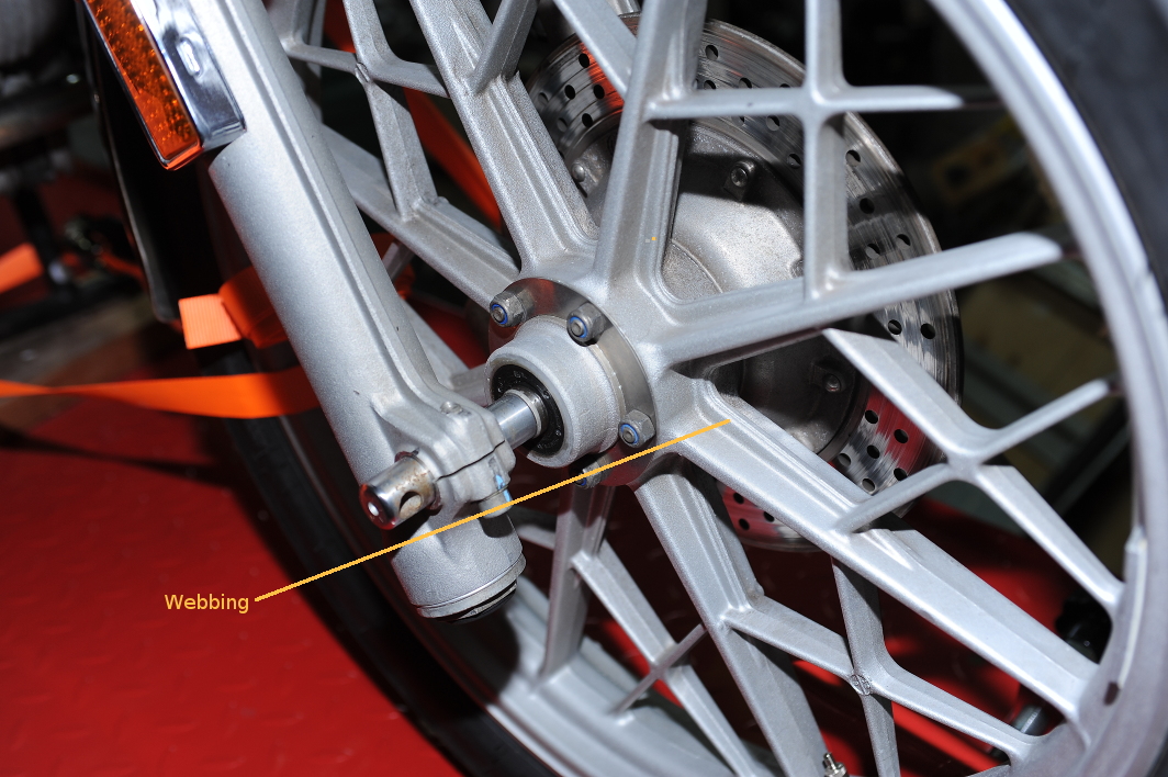
With the mufflers out of the way, it was time to remove the rear wheel.  I didn’t pull the fender, which prevented me from getting the wheel out until I removed the hydraulics access panel in the lift.  That gave me just enough room to drop the tire away from the bike.

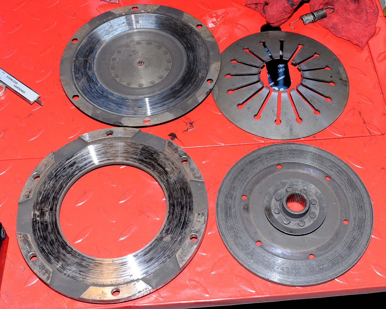
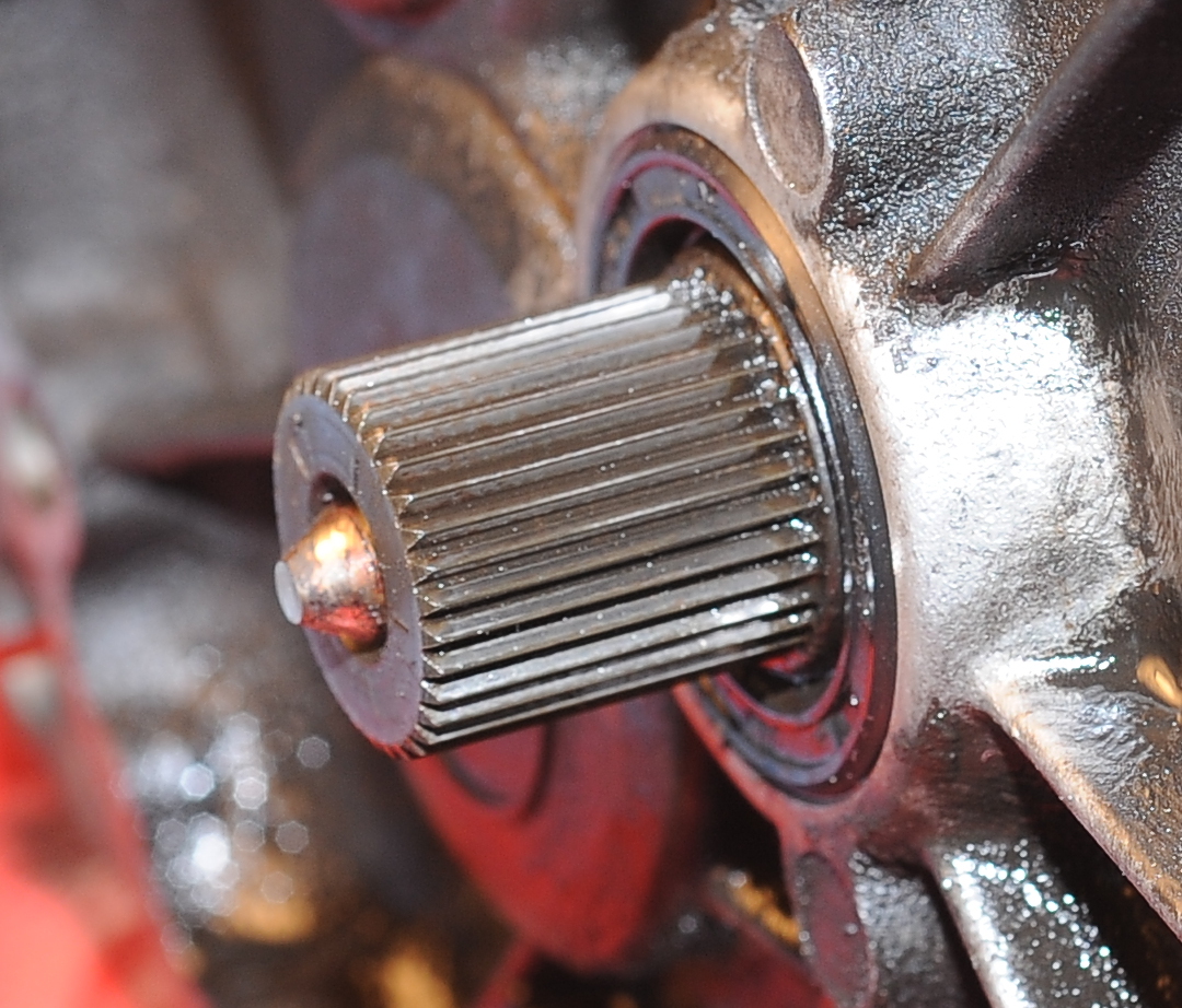
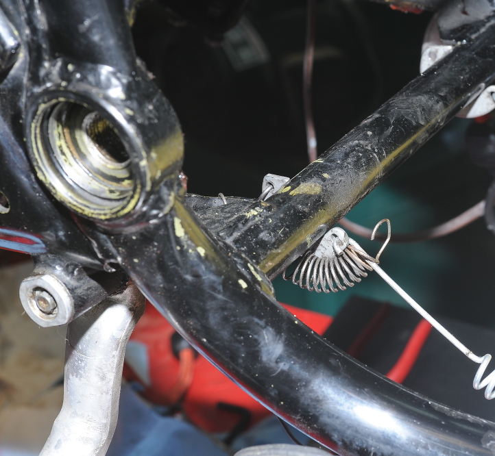
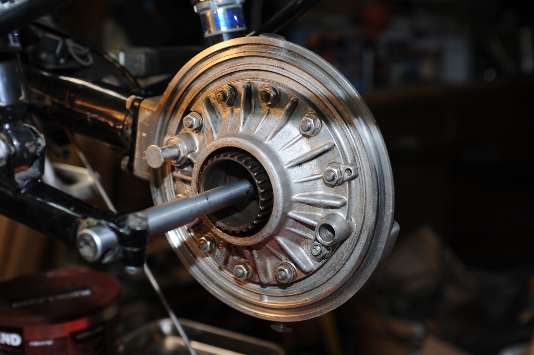
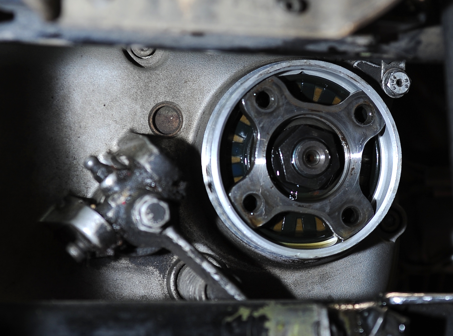
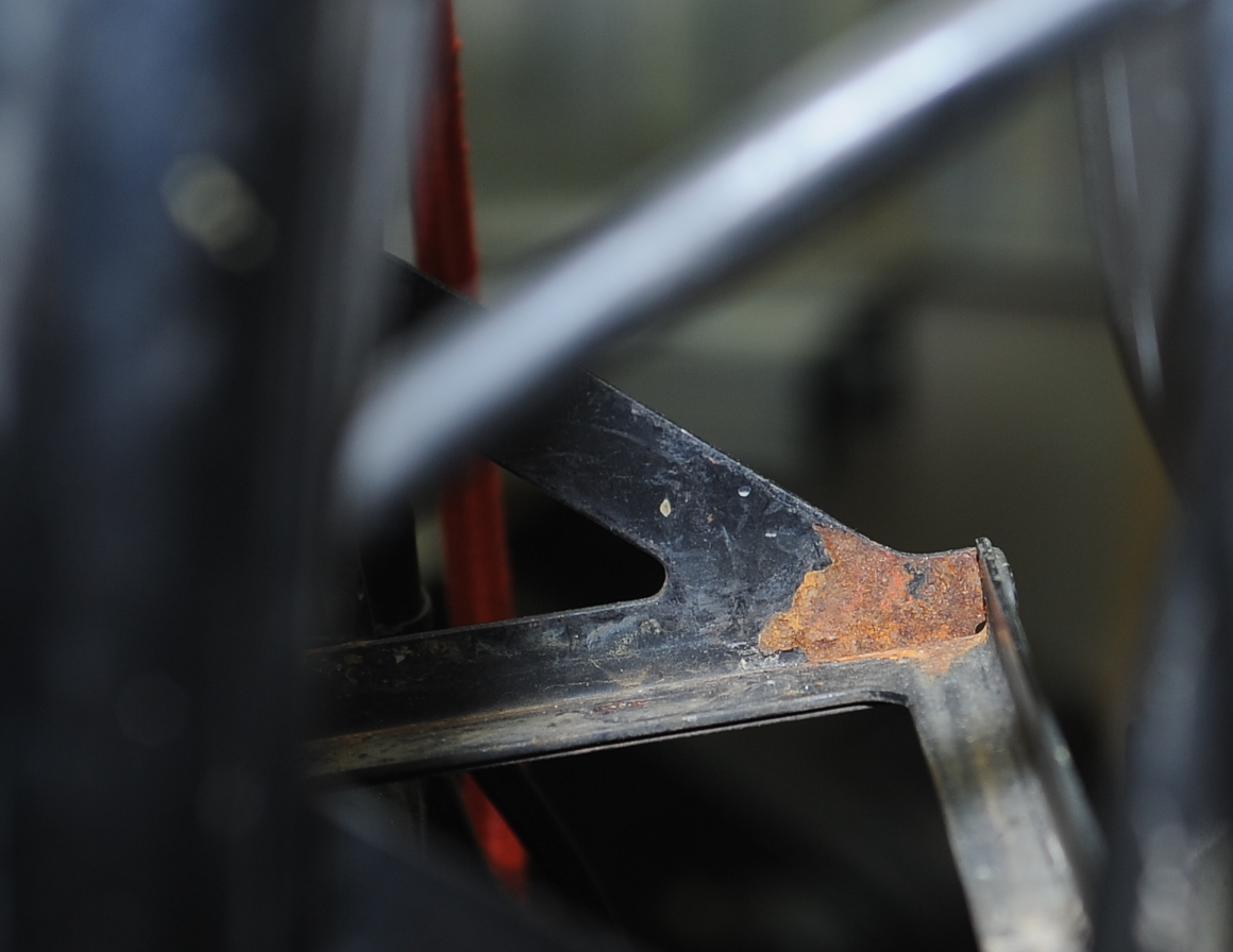
With the wheel out, it was pretty obvious that the splines are worn, and while they aren’t likely to fail immediately, I’m thinking I should look into having the splines repaired.  While it’s a bit hard to see through the grease, the wheel splines aren’t too bad.  As expected, the wheel bearings are shot.  However the outer races don’t appear to have spun, they’re press-fit in, so the hub should be in good shape.  Just needs new tapered roller bearings.

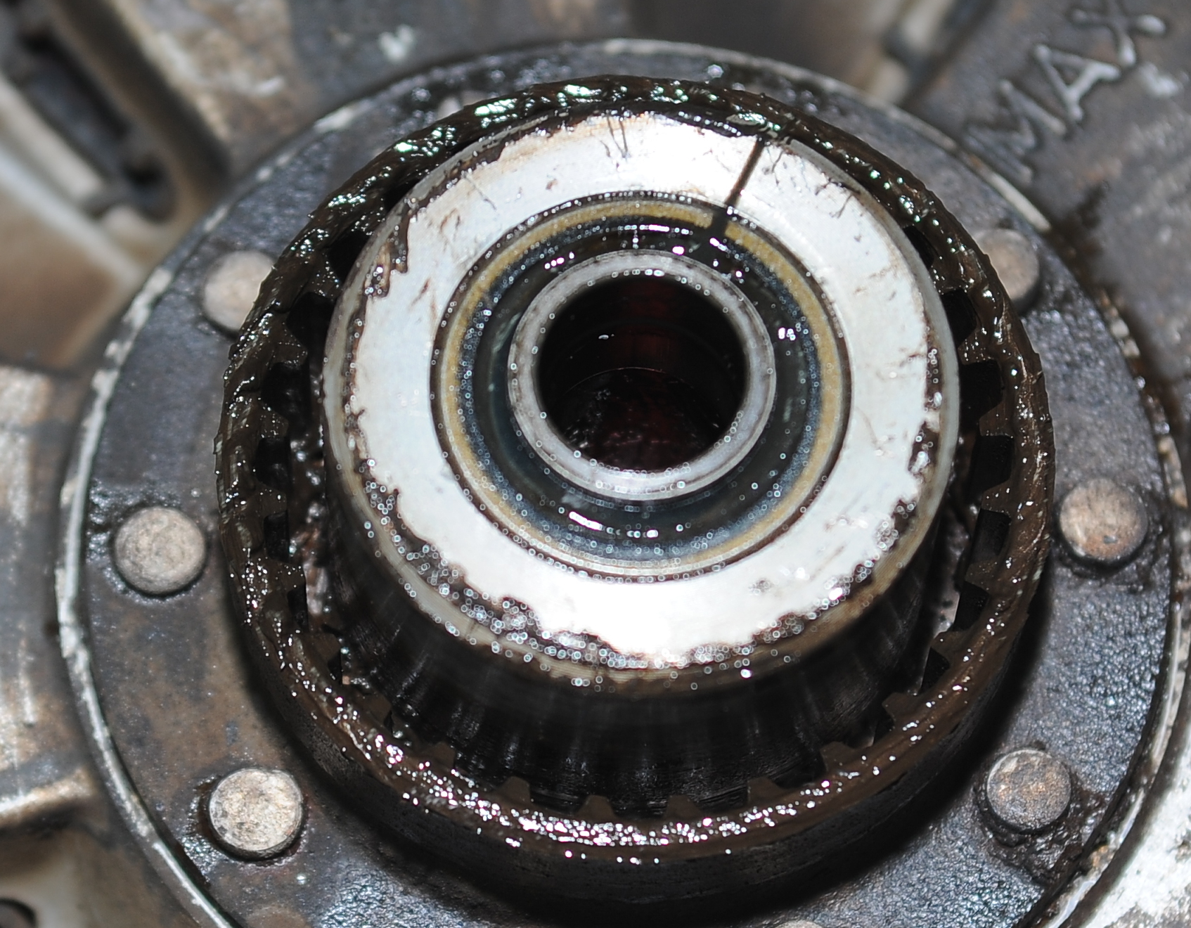
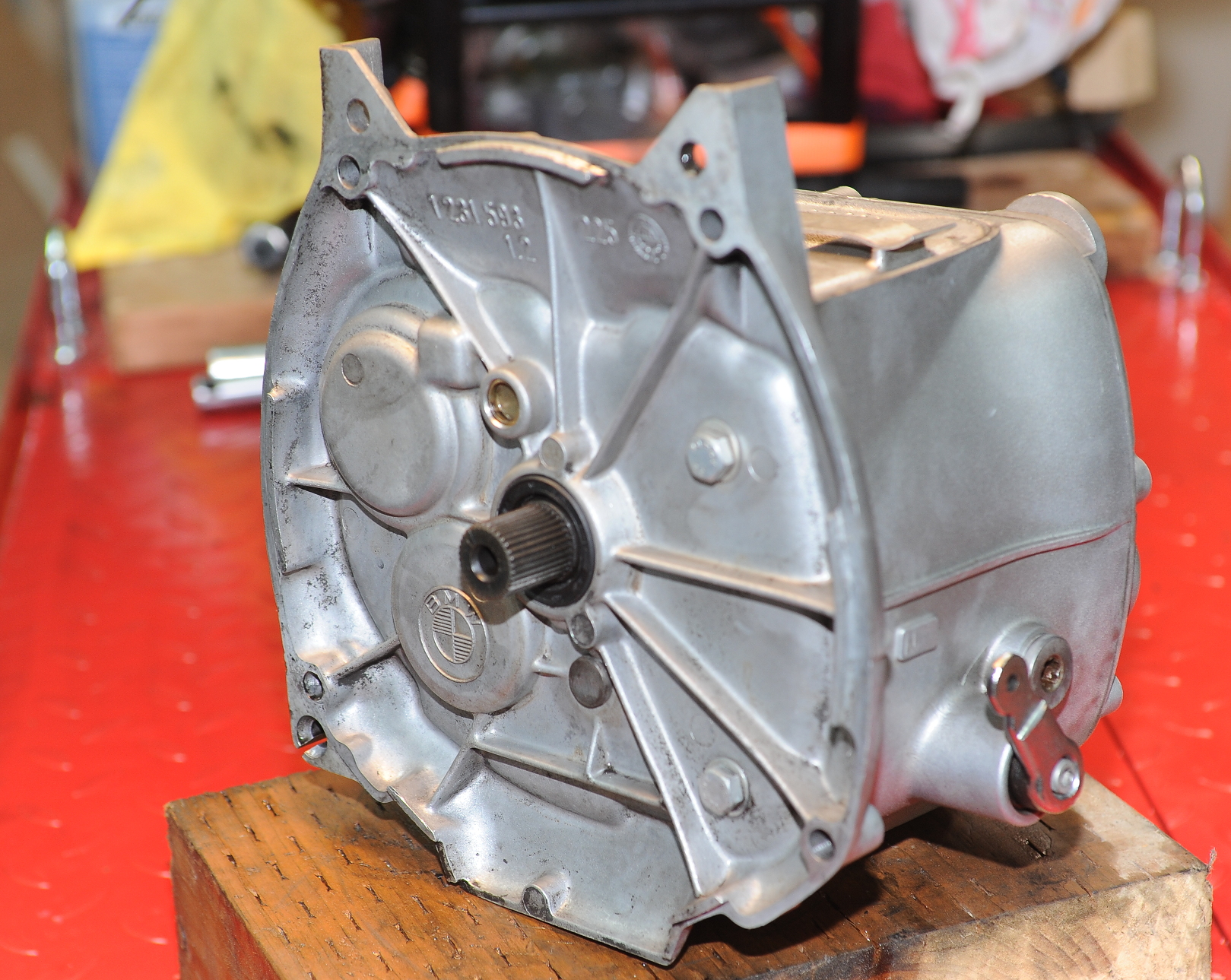
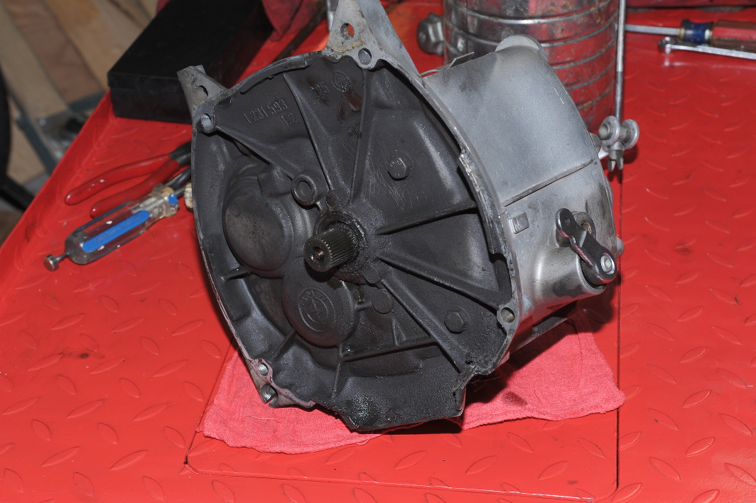
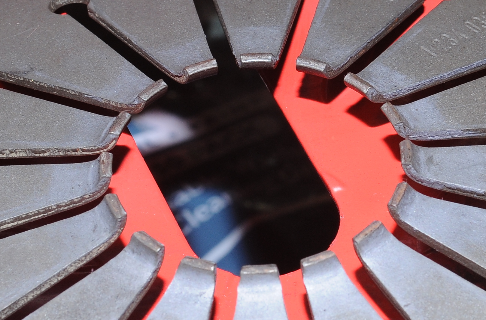
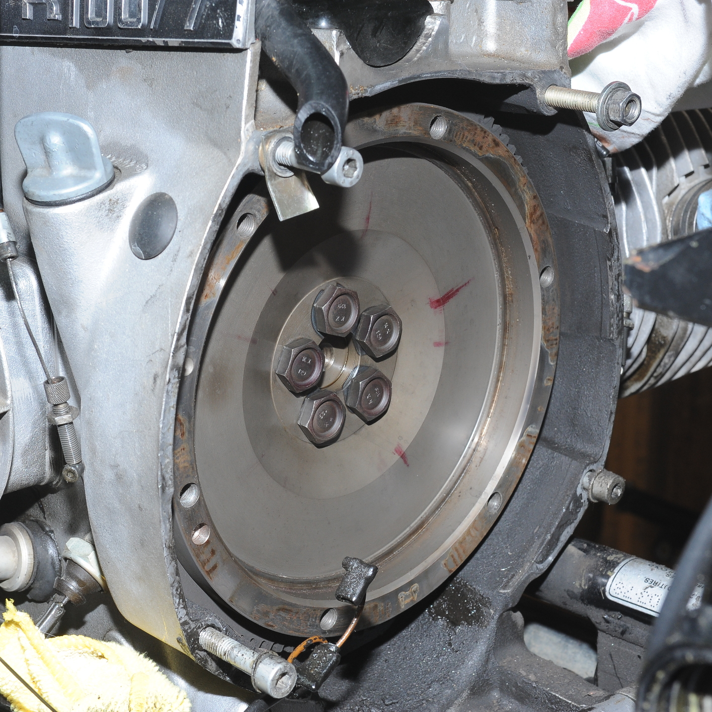
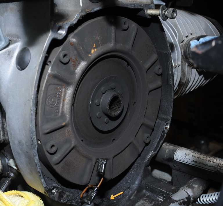
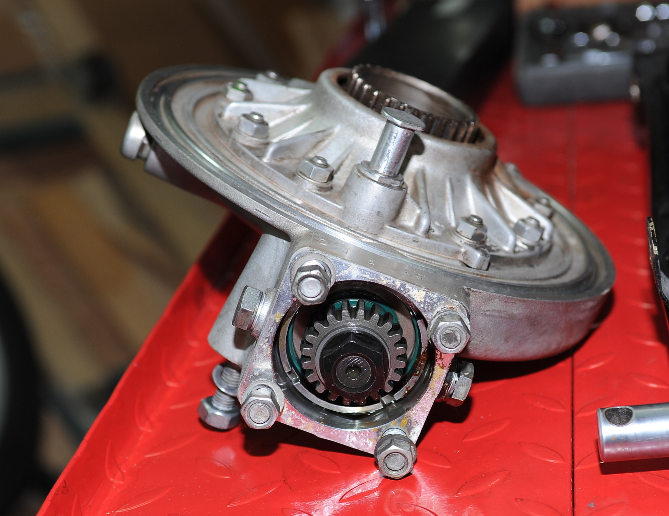
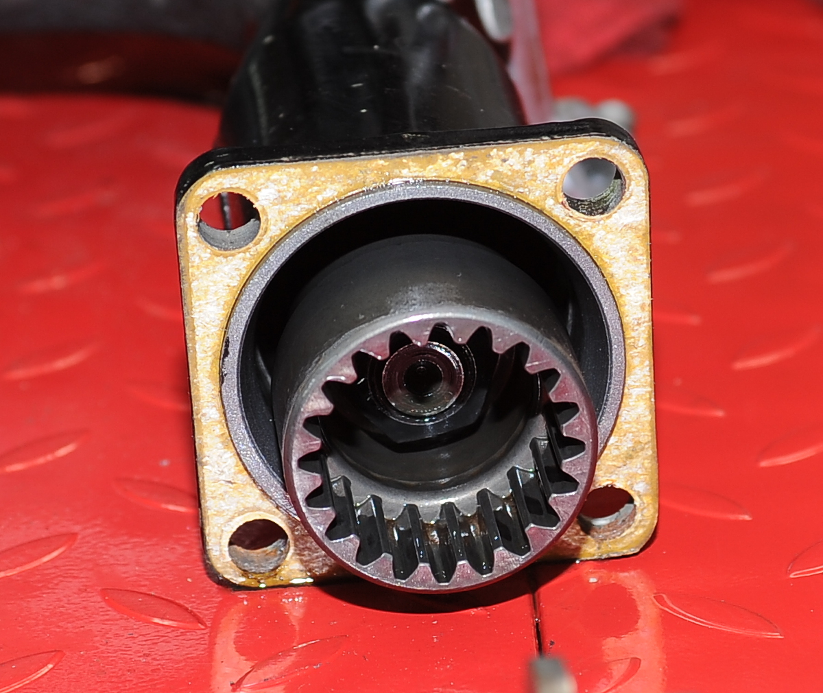
The final drive splines, while not yet pointy, are pretty thin.  One a positive note, the brake shoes look good, and there don’t appear to be any oil leaks from the final drive.  I’m not sure how much it would cost to repair, but a brand new drive is still available for under $1k.   I think I’m going to get at the clutch to to check the transmission input shaft and clutch splines before I try to solve this problem.

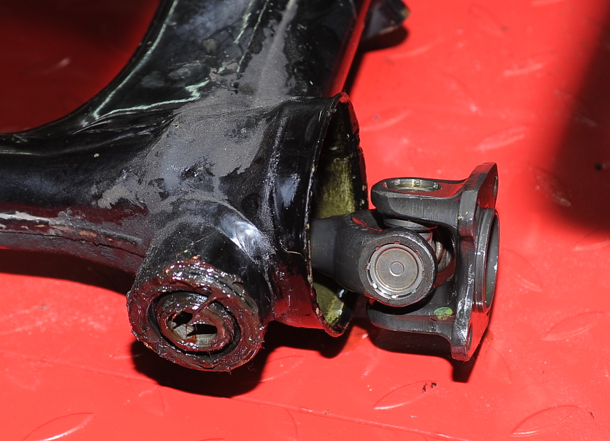
Next task, remove the swing arm.


We’re Home

Today I brought the bike home in my truck.  As the bike came from a much drier climate I’m sure the cold and rainy trip home came as a shock to the old girl.

The fairing was removed to make it easier to hook the front straps onto the frame — you can just see the windshield of the fairing behind the back tire.  The bike looks pretty nice without the Pacifico Aero XP fairing.   One interesting thing about the fairing install, all of the electrical stuff that was originally in the headlight bucket is now a black box where the headlight should be.  The box is Tupperware painted black!  Cool idea, actually, Tupperware as a waterproof electrical box.

During transport, the bike was held in place using four straps and was riding on it’s own suspension (i.e. no stand).  The straps were tightened down to compress the springs a bit.   We had three guys to get the bike into the truck, so that was easy.   I took it off without extra hands — just me and gravity.  It went fine, but it truly was white-knuckle time.